BTOW
This program is designed to control the high voltage of towers PMT's (Photo Multiplier Tubes). Each tube has an independent high voltage settings. Each PMT is connect to a CW-Base that controls the high voltage for the base. The CW-Base connects to a personal computer running Windows through a RS-485 serial line. The personal computer runs a LabView program that communicates to all CW-Bases in the system to set and monitor the high voltage on each PMT.
If you just want to know how to turn EMC high voltage ON and OFF, press here.
To run the high voltage control program just double click on the icon EMC high voltage control on the Windows desktop. The LabView program will start in a few seconds and the main screen of the program will appear. The main screen of the program looks like figure 1.

Figure 1.
Just after the program is started it asks if you are recovering from a computer crash. A small dialog box shown in figure 2 will appear

Figure 2.
When a computer crashes or the high voltage control is closed with the high voltage on, the PMT's are NOT shut down. So, if you answer YES the program reads a recovery file with the last used high voltage settings and supposes that the high voltage was on and starts monitoring it. If you answer NO, which should be the desirable answer, it establishes communication with the system and sets the high voltage to OFF.
After you answer this question, the program is ready to be used. The program has 4 main panels:
-
EMC Main Control
This panel controls the status of the high-voltage (On or OFF) and gives access to all configuration options.
-
PMT Boxes Status
This panel shows the current status of the PMT boxes
-
CW Bases Status
This panel shows the status of the CW-Bases inside a given PMT box
-
EMC Alarm Control
This panel is the alarm display.
This controls the status of the high voltage in the system. The panel looks like figure 3.

Figure 3.
The controls we have in this panel are:
-
ON/OFF - This is button turns ON and OFF the high voltage in the EMC.
-
OFF LED - This LED indicates the status of the high voltage. A RED LED labeled OFF indicates that the high voltage is OFF. If the high voltage is ON the LED is GREEN and it is labeled ON.
-
READ NOW - This button forces a complete readout of EMC. The regular readout is timed but it is possible to read the current high voltage anytime by pressing this button
-
RE-APPLY HV - This button resends the high voltage settings to EMC
-
CONFIGURATION - Goes to the configuration screen (expert only)
PMT Boxes Status
This panel shows the current status of the PMT boxes and looks like figure 4.

Figure 4.
There are 60 LED's in this panel. Each one indicates the current status of one PMT box. The Status are color coded and are :
-
Grey - PMT is OFF
-
GREEN - PMT is ON and Ok
-
YELLOW - PMT has triggered the temperature alarm
-
ORANGE - PMT has triggered the high voltage alarm
-
RED - PMT has triggered both temperature and high voltage alarms
CW Bases Status
This panel shows the status of the CW-Bases inside a given PMT box and looks like figure 5.

Figure 5.
There is 80 LED's corresponding to each CW-Base in a box. The box to be displayed can be selected by the control Box To Display and can go from 1 to 60. Each LED is color coded and the colors are:
-
Grey - CW-Base is OFF
-
GREEN - CW-Base is ON and Ok
-
YELLOW - CW-Base is above temperature limit
-
ORANGE - CW-Base high voltage if off limits
-
RED - CW-Base temperature and high voltage are off limits
It is also possible to check the readout information for a given CW-Base. This can be selected by the control CW Base and can go from 1 to 80. The information that are displayed for a given CW-Base is:
-
CWBase Soft Id - This is the id of the tower connected to the base
-
CWBase Id - This is the id of the CW-Base
-
CWBase S/N - This is the serial number of the PMT connected to the CW-Base
-
Voltage In - This is the voltage set.
-
Voltage Out - This the voltage readout
-
Temp - This is the temperature readout.
EMC Alarm Control
This panel is the alarm display and looks like figure 6.

Figure 6.
There are three LED's (main alarm, high voltage alarm and temperature alarm). If the LED is GREEN it means everything is ok. If it is RED it means that the alarm was triggered for that variable.
There are two buttons and one switch:
-
Sound ON/OFF - Turns ON/OFF the alarm sound. Should be kept ON
-
Clear Alarms - Clear the Alarm status until next readout.
-
Clear Status - Clear CW-Bases status until next readout. Also clear the alarms
Expert Operation
The high voltage control program has two configuration files that need to be created prior to the utilization of the program. Those files are:- default.ini
This is the basic configuration file. In this file there is information about the high voltage database file, which box and CW-Base need to be turned on, serial line settings and other configuration stuff. This file do not need to be edited by hand. There is a special window in the high voltage program that can be used to modify this file.
- InitData.csv
This is the high voltage database (the name can be different). This contains all information about each individual base. The csv extension permits to open this file on Microsoft Excel to be modified. Details about this file can be found here.
In the EMC Main Control panel there is a button called Configuration that opens a window with all possible configuration of the program. This windows can be accessed only if the high voltage is OFF for safety reasons.
The configuration window looks like figure 7.

Figure 7.
There are 4 panels in this window
-
Serial port config - Configures the serial line
-
Baud Rate - Sets the serial line baud rate (bits per second)
-
Delay fro ON/OFF - Sets the delay (in micro seconds) after send a command ON/OFF to the serial line
-
Delay for Readout - Sets the delay (in micro seconds) after send a readout command to the serial line
-
-
EMC log control - Controls the high voltage log information
-
Time between logs (min) - Sets the time between creation of log files (minutes)
-
Time between inquire (min) - Sets the time between consecutive readouts (minutes)
-
Path to save logs - Directory where the log files will be saved
-
-
EMC Alarm control - Controls the voltage and temperature alarms
-
High Voltage Alarm - Controls the high voltage alarm
-
On/Off - turns ON and OFF the high voltage alarm
-
Number of CW Bases/Box - If the number of CW Bases in a box with bad high voltage is above this limit it triggers the alarm for that PMT box.
-
Max deviation (percentage) - Maximum deviation from nominal value to trigger the alarm for a given CW Base
-
-
Temperature Alarm - Controls the temperature alarm
-
On/Off - turns ON and OFF the temperature alarm
-
Number of CW Bases/Box - If the number of CW Bases in a box with bad temperature is above this limit it triggers the alarm for that PMT box.
-
Max Temp - Maximum temperature value to trigger the alarm for a given CW Base
-
-
-
Extra HV settings
-
Enable recovery - If this option is ON the program tries to reprogram the high voltage if the readout of a given CW-Base is BAD. It tries to do it 5 times for each BAD CW-Base.
-
Voltage to ramp down - This is the voltage that is programmed in the CW-Bases when the high voltage is turned OFF.
-
High Voltage Database file - File which contains the high voltage settings for each CW-Base
-
And there are 6 buttons
-
READ from file - Read configuration from a given file
-
Save to file - Save configuration to a given file
-
Cancel - Cancel modifications and returns to main screen
-
Ok - Save modifications to default.ini, activate modifications and returns to main screen
-
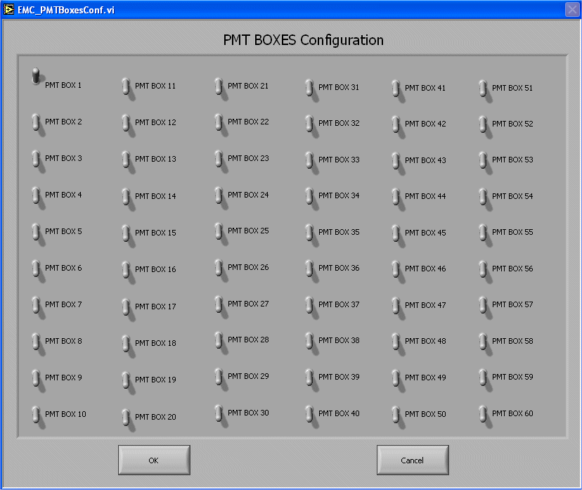
PMT Box configuration - Opens a window where each PMT box can be turned ON and OFF (see figure 8)
-
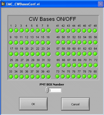
CW Bases Configuration - Opens a window where each individual CW-Base in each box can be turned ON and OFF (see figure 9)
Figure 8.
Figure 9.
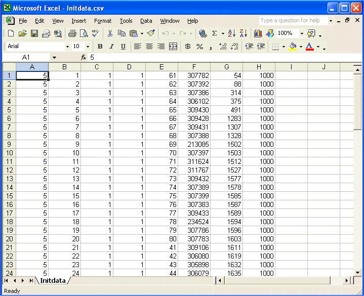
The high voltage database is a TEXT file that contains the high voltage information for each CW-Base. The default name is InitData.csv. The csv extension permits to open the TEXT file directly on Microsoft Excel, which makes it easier to edit. The file looks like figure 10.

Figure 10.
There are 8 columns in this file named:
-
Column A - The serial port number of each CW-Base
-
Column B - The software Id of the tower connect to the CW-Base
-
Column C - The module number
-
Column D - The PMT box number
-
Column E - The position of the CW-Base inside the PMT box
-
Column F - The serial number of the PMT connected to the CW-Base
-
Column G - The Id of the CW-Base
-
Column H - The high voltage set for that CW-Base
The log file
The log file is a TEXT file that contains the readout information for each CW-Base. It has the same format of the database plus three columns:
- Column I - The Voltage read
- Column J - The temperature read
- Column K - Status of the CW-Base

0 means that the CW-Base is OFF 
1 means that the CW-Base is Ok 
2 means High voltage off limits 
3 means Temperature off limits 
4 means High Voltage and temperature off limits
The log file is saved with the name EmcLog.DATE.TIME.txt where DATE and TIME are the date and time the log was created. There is a ROOT macro called HVReadLog.C that reads all log files in the log directory and create a series of plots with those information. To run the HVReadLog.C just double click the HVReadLog icon on the Windows desktop. A menu of plots will appear on the screen and just follow that menu to get the log plots.
1. How to turn ON/OFF the high voltage
To turn ON the High Voltage
-
If HV is OFF
-
Answer NO to the "Are you recovering from a computer crash with the high voltage on?" dialog box
-
Press the ON/OFF button in the EMC Main Control panel
-
The program sends the high voltage settings to all CW-Bases
-
The program reads out all CW-Bases
-
Sometimes it reads out too fast and some of the bases may not reach the nominal high voltage value, so the alarm may be triggered. In this case, press the READ NOW button to make a new readout.
-
-
-
The ON/OFF LED will turn GREEN and will be labeled ON
-
High voltage is set.
-
A new readout is being done every few minutes. If something happens one of the alarms will be triggered.
-
If HV is ON and you are recovering from a crash
-
Answer YES to the "Are you recovering from a computer crash with the high voltage on?" dialog box
-
The ON/OFF LED will turn GREEN and will be labeled ON
-
High voltage is set
To turn OFF the High Voltage
-
Press the ON/OFF button in the EMC Main Control panel
-
The ON/OFF LED will turn RED and will be labeled OFF
To test a new box (or a set of new boxes) it is necessary to follow the steps below:
- Create a new database file with the bases configuration
- The database file is usually called InitData.csv and it
is located in the main directory of the high voltage program. The format
of the file is shown here
- Create new lines depending on the number of bases you intend to test. The important numbers that need to be careful entered in the file to test new boxes are the serial port number (5 at WSU and 3 at BNL), the PMT box number, the position in the box, the CW-Base number and the high voltage. The other columns are just for display and they don't matter a lot for testing.
- Save the file. A comment here: I usually create one database file for each box and I give it the name InitData.boxXX.csv. In this case, when I want to test two different boxes I just copy all the information of these files to the final InitData.csv
- The database file is usually called InitData.csv and it
is located in the main directory of the high voltage program. The format
of the file is shown here
- Start the high voltage control program
- Answer NO to the "Are you recovering from a computer crash with the high voltage on?" dialog box
- BEFORE turn on the high voltage Press the CONFIGURATION button in the EMC Main Control panel
- Press the PMT BOX CONFIGURATION button in the Expert
Window
- The PMT Boxes Configuration window will appear
- Turn ON only the boxes that will be tested
- Click OK
- Press the CW Bases Configuration button in the Expert
Window
- The CW Bases ON/OFF screen will appear
- Select the box you will test and make sure all bases are on (GREEN LED)
- Press OK
- Press OK button in the Expert Window
- Press the ON/OFF button in the EMC Main Control panel to turn the high voltage ON
- If everything is OK the program will start reading the high voltage from the boxes.

