BTOF
Barrel Time-of-Flight Detector
BTOF Operations (incl. slow controls)
Barrel Time-of-Flight Operations
Barrel Time-of-Flight Database Initialisation at the Start of Run
1. Find two primitive macros: $STAR/StRoot/StBTofPool/dbase/macros/tof_reload.C & tofsim_reload.C. Better to copy the whole macro directory to your own directory.
2. Change the old timestamp to the new timestamp for this year. Use Run25 as an example:
These are timestamp listed for Run25.
- Geometry tag has a timestamp of 20241210
- Simulation timeline [20241215 , 20241220]
- Database initialization for real data [20241225 , ...]
"gROOT->ProcessLine(".x table_reupload.C(\"Calibrations_tof\", \"tofINLSCorr\", \"ofl\", \"2024-12-25 00:00:00\",\"2024-12-26 00:00:00\"");"
This is the example code inside the macro. It means copy the parameter tables from the first time to second time.
The timestamp used in tof_reload.C. should be related with Real Data Timestamp.
The timestamp used in tofsim_reload.C should be related with Simulation Timestamp.
We could ask Gene for advice.
3. Run the command: setenv DB_ACCESS_MODE write
4. root4star -b -q -l tof_reload.C & tofsim_reload.C
Type "Yes" for every entry.
On-call expert
Last updated: March 24th 2010
How To Clear TOF Errors
TOF on-call expert for this week: Yi Zhou (cell: 631-965-6132)
Frank Geurts (Apartment: 631-344-1042)
Important Notes:
The Anaconda window should always running at the TOF Station! Do Not Close this window.
Shift crews must check the Warning and Error sections of the Anaconda window after every new run is begun. Warnings will automatically cleared when runs are begun. If an Error is not cleared automatically when a new run is begun, see sections 4 and 1 below.
For all TOF alarms or errors, leave a note in the shift log. Be detailed so the experts will understand what happened and you actually did.
Never click the red 3 button in the Anaconda window or power cycle a tray during a run, only when the run is stopped.
Additional actions:
- Electronics errors and/or bunchid errors
Stop the run and determine which tray has the issue (there likely will be a yellow LV current alarm). Clear all (other) errors in Anaconda by pressing the red (3) button. The affected tray will most likely turn gray in Anaconda. In Anaconda, turn off "Auto-Refresh" (in "Command" menu). Go to the main voltage control GUI, turn the LV for that tray off, wait 10 seconds, and then turn the LV for that tray on again. Wait 60 seconds. Then click the red (3) button in the Anaconda window. The tray status should turn green. Turn on "Auto-Refresh" again. Start a new run. Make a note in the shift log. If the problem isn't fixed, then call the expert. - Yellow alarm at LV power supply associated with a tray.
First, check TOF QA plots and look for electronic errors or bunchid with electronic errors. If there are errors, then follow step 1. Otherwise don't call an expert, just make a note in the shift log. - Missing tray or half-tray in TOF online plots (specifically Multiplicity plots), follow procedure 1.
- In the TOF_MON GUI (Anaconda II):
- If you see red errors and/or the online plots indicate problems, stop and restart run. If error doesn't get cleared by this, make sure that all of the small LV circles in the main voltage GUI are green. If not, follow procedure 1 above. Otherwise, call the expert.
- If you see yellow alarms, no need to call experts, these clear automatically at the beginning of the next run.
- If it is grey alarm, click the "Refresh" button (left of the "1" button) to see if this clears it, otherwise follow procedure 1.
- TOF readout 100% DAQ errors and one of the RDO 1-4 lights on the TOF DAQ receiver is not responding (LED is black instead of blue or purple). The cure is to stop the run, mark it bad, and start a new run. Nothing else is required. This has worked 100% of the time so far. Make a note in the shift log.
- Gas alarm on FM2, which is for iso-butane gas.
When it's cold, the pressure on FM2 will decrease and may cause alarms. In this case, no need to call expert. - If you see the LV off, i.e. dots are blue. (In the normal situation, the dots are green, indicating the LVs are on), please call expert.
- TOF HV slow control lost communication, please leave a note in the shift log, and follow the procedure in the trouble shooting of HV manual to fix it. Call expert for help in case you do not fix the problem.
Slow Controls
Slow Controls Detector Operator Manuals
by Betrand J.H. Biritz (linked version: Jan.5, 2010)
EPICs interface
HV manual
LV manual
BTOF-MTD-ETOF operation instruction documents (Run21 and After)
- The instructions for the control room can be found at STAR operation page:
- STAR Operation (BTOF/MTD/ETOF) both .doc and .pdf file are attached
- Expert Knowledge Manual (Only for Oncall Expert)
- Expert Knowledge Base (Updated on 2024 April) both .doc and .pdf file are attached
- Note that, Anaconda was not in use since Run2021, all the procedures related to Anaconda can be ignored at this moment unless we include Anaconda back to the operations.
===============================================================
- Some old but more comprehensive collection about bTOF/MTD/VPD operations can be found at Bill Lope’s Blog: https://drupal.star.bnl.gov/STAR/blog/llope:
-
- TOF OPS: systec channel assignments - January 25., 2014
- TOF OPS: How to check if a LV channel has become disabled - January 28., 2014
- TOF OPS: checking/restarting recoveryd - May 5., 2013
- TOF OPS: How to restart the systec without rebooting tofcontrol - March 12., 2013
- TOF OPS: How to collect the TOF L0 Mult phase scan data - March 12., 2013
- TOF OPS: TOF/MTD power supply info - January 19., 2013
- TOF OPS: Gas Usage - January 18., 2013
- TOF OPS: IP addresses - January 15., 2013
- TOF OPS: editing the MTD and TOF mask maps for the DAQ data-checking routines - December 3., 2012
- TOF OPS: How to mask a tray out of Anaconda - April 8., 2012
- TOF OPS: How to get daq files if HPSS is down - December 14., 2011
- TOF OPS: Switching from N2 mode to freon-only purge mode - December 2., 2011
- TOF OPS: change gas system from recirc to purge or from purge to recirc - October 25., 2011
- TOF OPS: RDO mapping - October 14., 2011
- TOF OPS: How to mask TOF trays in/out of the L0 tofmult trigger - May 13., 2011
- TOF OPS: How to begin N2 Purging of the gas system - April 19., 2011
- TOF OPS: Gas System History - April 19., 2011
- TOF OPS: How to use the ArchiveViewer - April 19., 2011
- TOF OPS: HV_logger columns and GUI info - March 5., 2011
- TOF OPS: How to enable/disable o2/h2o monitoring - March 5., 2011
- TOF OPS: How to collect the data and set the VPD TAC offsets in the Trigger system - February 11., 2011
- TOF OPS: How to collect the VPD HV scan data - February 11., 2011
- TOF OPS: How to set up three default VPD HV sets for a gain calibration - February 11., 2011
-
Run 16 TOF + MTD Operations Documents:
This page holds TOF and MTD operations documents used during Run-16. Previous versions and possibly current versions may be found on Run-15's equivalent page. [ie: If you do not see the document attached to the bottom of this page, it has not been updated since last run and may be found on the Run-15 page.]:
Run 15 TOF+MTD Operations Documents
Run 15 TOF + MTD Operations Documents
This page is dedicated to hosting documents to aide in the operation of the TOF, MTD, and VPD subsystems. Listed below are a list of the documents attached to this page and a brief description. The .docx files are listed to update the documents as needed.
The first part of the document describes how to restart the canbus interface and the processes dependent on it (recoveryd and anaconda).
The second part adds a powercycle of the interface to the procedure.
Expert_Knowledge_Base.pdf (document formerly known as Etc.pdf)
A collection of tidbits for TOF+MTD folk. Not quite intended for det. operators.
MTD_HVIOC_Restart.pdf
This guides the detector operator on how to restart an HVIOC for the MTD.
If you want to get super fancy with restarting IOCs, you might want to check their saved states in the ~/HV/HVCAEN*/iocBoot/save_restore_module/*.sav* and see what the IOC is initializing with. The same thing applies for the LV (MTD/LV/LVWiener*/iocBoot/save_restore_module/) and TOF.
MTD_Power_Cycle_Procedure.pdf
Instructions for the detector operator on performing a LV powercycle.
Recoveryd_Checking_Restarting.pdf
This document describes how to check and restart recoveryd.
Responding_To_DAQ_Powercycle_Requests_Monitoring_And_Clearing_Errors.pdf (Formerly known as General_Instructions)
This document is used as a guide to respond to DAQ powercycle requests and monitoring and clearing errors given by DAQ.
TOF_Freon_Bottle_Switchover_Procedure.pdf
The document decribes how to monitor the freon and what to do when it runs out.
TOF_HVIOC_Restart.pdf
To guide the detector operator through a TOF HVIOC restart.
TOF_Power_Cycle_Procedure.pdf
Instructions for the detector operator on performing a LV powercycle.
Run 16 TOF+MTD Operations Documents
This page holds TOF and MTD operations documents used during Run-16. Previous versions and possibly current versions may be found on Run-15's equivalent page. [ie: If you do not see the document attached to the bottom of this page, it has not been updated since last run and may be found on the Run-15 page.]
Run 16 TOF + MTD Operations Documents
This page is dedicated to hosting documents to aide in the operation of the TOF, MTD, and VPD subsystems. Listed below are a list of the documents attached to this page and a brief description. The .docx files are listed to update the documents as needed.
The first part of the document describes how to restart the canbus interface and the processes dependent on it (recoveryd and anaconda). (This document has been updated since Run-15)
The second part adds a powercycle of the interface to the procedure.
Expert_Knowledge_Base.pdf (This document has been updated since Run-15)
A collection of tidbits for TOF+MTD folk. Not quite intended for det. operators.
MTD_HVIOC_Restart.pdf
This guides the detector operator on how to restart an HVIOC for the MTD.
If you want to get super fancy with restarting IOCs, you might want to check their saved states in the ~/HV/HVCAEN*/iocBoot/save_restore_module/*.sav* and see what the IOC is initializing with. The same thing applies for the LV (MTD/LV/LVWiener*/iocBoot/save_restore_module/) and TOF.
MTD_Power_Cycle_Procedure.pdf
Instructions for the detector operator on performing a LV powercycle.
MTD_LVIOC_Restart.pdf (This document is new since Run-15)
To guide the detector operator through a MTD LVIOC restart.
Recoveryd_Checking_Restarting.pdf
This document describes how to check and restart recoveryd.
General_Instructions.pdf (This document has been updated since Run-15) (The document formerly known as "The document Formerly known as General_Instructions" or Responding_To_DAQ_Powercycle_Requests_Monitoring_And_Clearing)
This document is used as a guide to respond to DAQ powercycle requests and monitoring and clearing errors given by DAQ.
TOF_Freon_Bottle_Switchover_Procedure.pdf
The document decribes how to monitor the freon and what to do when it runs out.
TOF_HVIOC_Restart.pdf (This document has been updated since Run-15)
To guide the detector operator through a TOF HVIOC restart.
TOF_LVIOC_Restart.pdf (This document is new since Run-15)
To guide the detector operator through a TOF LVIOC restart.
TOF_Power_Cycle_Procedure.pdf
Instructions for the detector operator on performing a LV powercycle.
Run19 TOF and MTD operation instruction documents
This page summarizes all the documents for the BTOF and MTD operation.
Run20 TOF and MTD operation instruction documents
This page summarizes all the documents for the BTOF and MTD operation during Run 20.
Attached files:
- version 1/6/20 by Zaochen Ye
Know issues:
- page 9 of version 1/6/20
- the link to the TOF NPS should be https://drupal.star.bnl.gov/STAR/subsys/tof/btof-hardware/tof-nps-maps
TOF Error Handling
Last updated: March 23nd 2010
TOF Error Handling
TOF on-call expert for this week: Bill Llope (Apartment: 631-344-1042, Cell: 713-256-4671)
The Anaconda window should always be running on the TOF work station. It keeps a log of important operating conditions and automatically clears most type of electronics errors at the beginning of each run.
The most important indication of the TOF system "health" are the online plots. They should be checked after the beginning of each run.
Shift crews should check the Warning and Error sections of the Anaconda window to see that Warnings and Errors are being cleared automatically at the beginning of each run.
Please make a note of all TOF alarms or any error not automatically cleared by Anaconda in the shift log. Please include enough information so the experts can understand what happened and what you actually did.
Never click the red 3 button in the Anaconda window or power cycle a tray during a run, only when the run is stopped.
Additional actions:
- Electronics errors and/or bunchid errors
Stop the run and determine which tray has the issue (there likely will be a yellow LV current alarm). Clear all (other) errors in Anaconda by pressing the red (3) button. The affected tray will most likely turn gray in Anaconda. In Anaconda, turn off "Auto-Refresh" (in "Command" menu). Go to the main voltage control GUI, turn the LV for that tray off, wait 10 seconds, and then turn the LV for that tray on again. Wait 60 seconds. Then click the red (3) button in the Anaconda window. The tray status should turn green. Turn on "Auto-Refresh" again. Start a new run. Make a note in the shift log. If the problem isn't fixed, then call the expert. - Yellow alarm at LV power supply associated with a tray.
First, check TOF QA plots and look for electronic errors or bunchid with electronic errors. If there are errors, then follow step 1. Otherwise don't call an expert, just make a note in the shift log. - Missing tray or half-tray in TOF online plots (specifically Multiplicity plots), follow procedure 1.
- In the TOF_MON GUI (Anaconda II):
- If you see red errors and/or the online plots indicate problems, stop and restart run. If error doesn't get cleared by this, make sure that all of the small LV circles in the main voltage GUI are green. If not, follow procedure 1 above. Otherwise, call the expert.
- If you see yellow alarms, no need to call experts, these clear automatically at the beginning of the next run.
- If it is grey alarm, click the "Refresh" button (left of the "1" button) to see if this clears it, otherwise follow procedure 1.
- TOF readout 100% DAQ errors and one of the RDO 1-4 lights on the TOF DAQ receiver is not responding (LED is black instead of blue or purple). The cure is to stop the run, mark it bad, and start a new run. Nothing else is required. This has worked 100% of the time so far. Make a note in the shift log.
- Gas alarm on FM2, which is for iso-butane gas.
When it's cold, the pressure on FM2 will decrease and may cause alarms. In this case, no need to call expert. - If you see the LV off, i.e. dots are blue. (In the normal situation, the dots are green, indicating the LVs are on), please call expert.
- TOF HV slow control lost communication, please leave a note in the shift log, and follow the procedure in the trouble shooting of HV manual to fix it. Call expert for help in case you do not fix the problem.
TOF On-call expert
Last updated: February 8th 2010
Expert information is also below:
Today through Thursday (Feb 09-Feb 11th):
Feb 12th 0:30-7:30 shift is included.
Lijuan Ruan: 510-637-8691 (cell)
I will leave for APS meeting on Friday morning.
Friday-Saturday (Feb 12th - 13th):
Feb 14th 0:30-7:30 shift is included.
Yi Zhou: 631-344-1014 (apt #), 631-344-7635 (office).
Sunday-Monday (Feb 14th-15th):
Feb 16th 0:30-7:30 shift is included.
Geary Eppley: 713-628-2738 (cell)
Jo will arrive on the night of Feb 15 th, so for Feb 16th shift, please call
Jo Schambach: 631-344-1042 (Apt #) for help.
For all TOF alarms, leave a note in the shift log. Additional actions:
- Gas alarm on FM2, which is for iso-butane gas.
When it's cold, the pressure on FM2 will be changed, this will lead to the flow of isobutene dropping, thus give us alarms. In this case, no need to call expert. We expect isobutene to run out sometime in Feb. - Temperature alarms on the LV powersupply, no need to call expert.
- Electronic errors or bunchid errors with electronic errors
Stop the run and determine which tray has the issue (there might be a yellow LV current alarm). Turn the LV off, wait 10 seconds and then turn the LV on again. After waiting 10 seconds click the red 3 button in the Anaconda window, the tray status should turn green. Start a new run - if the problem isn't fixed then call the expert. - Yellow alarm at LV poweruspply associated with a tray.
First, check TOF QA plots and look for electronic errors or bunchid with electronic errors. If there are then follow step 3, otherwise don't call but make a note in the shift log. - Missing tray on online plots, call expert.
- If you see the LV off, the dots are blue. (In the normal situation, the dots are green, indicating the LVs are on), please call expert.
- In the TOF_MON GUI:
- If you see red errors, stop and restart run. If error doesn't get cleared by this, call expert.
- If you see yellow alarms, no need to call experts.
- If it is grey alarm, call the expert.
- TOF HV slow control lost communication, please leave a note in the shift log, and follow the procedure in the trouble shooting of HV manual to fix it. Call expert for help in case you do not fix the problem.
TOF noise rate pattern
BTOF and MTD noise patterns are determined from dedicated TOF noise runs. Such runs are typically executed once per day -time permitting- during each RHIC Run at times when there is no beam stored in the rings. With a dedicated trigger 4M events are collected with BTOF and MTD systems both included with HV switched on.
The results are archived at this location: https://www4.rcf.bnl.gov/~geurts/noise/
Input data:
- TRG Setup: pedAsPhys_tcd_only
- Number of events: 4M
- Detectors: tof {mtd, etof} dan trg
- RHIC status: no beam
- Detector status: HV fully ramped up
recent example in STAR Runlog: Run 24151017
Ideally, shift crew note in the Shift Log that these runs are successfully executed TOF noise runs. Make sure to check the Shift Log and/or SlowControls to verify.
Potential error modes:
- HV was not ramped up (check slow controls status)
- Beam was still in RHIC or beam injection happened (check shift log or RHIC beam current info in slow controls)
- Not all relevant detectors have been included (check list of detectors for this run in Run Log)
BTOF Hardware
BTOF Hardware & Electronics
- Bad Tray History (Aug. 20, 2021)
Tray 102 has a bad POS HV cable. It is behind the TPC support and cannot be repaired.

Run 10 start  58
      end    10
Run 11 start  25
      end    25
Run 12 start  95
      end    95
Run 13 start  46 106
      end    46 106
Run 14 start  20  22  35 103
      end    20  22  35  78 103
Run 15 start  38  41
      end    38  41
Run 16 start 105
      end   105
Run 17 start  36  45  80
      end    36  45  80  91 116
Run 18 start   8  43 116
      end     2   8  40  43 116
Run 19 start  30  34             (water leak on THUB NW trays 21-50)
      end    22  25  27  30  34  67  97
Run 20 start  22  25  67
      end     8  22  25  48  64  67  88 101 118 119
Run 21 start   8  22  48  64  67  88 101 118 119
      end     8  22  48  49  64  67  88 101 118 119

pp500/510 history:

Run  9  10 pb-1
   11  37 pb-1
   12  82 pb-1
   13 300 pb-1
   17 320 pb-1
   22 400 pb-1 (BUR)

Current bad trays:

 8 - 8:0 bunch id error, 8:1 missing
22 - no canbus
48 - 48:0,1 missing
49 - no canbus
64 - TDIG 59 no response
67 - may be ok now
88 - 88:0 missing
101 - 101:0 missing, 101:1 bunch id error
118 - bad LV connection, seems ok now
119 - 119:0 HPTDC 0x6 error
- Electronics Documentation on old server (pending transition to drupal)
- Wiener PL512 Technical Manual
- default SNMP community names for all TOF and MTD power supplies: {tof-pub, tof-priv, admin, guru}:
[geurts@tofcontrol ~]$ snmpwalk -v 2c -m +WIENER-CRATE-MIB -c guru tof-lvps1 snmpCommunityName
WIENER-CRATE-MIB::snmpCommunityName.public = STRING: "tof-pub"
WIENER-CRATE-MIB::snmpCommunityName.private = STRING: "tof-priv"
WIENER-CRATE-MIB::snmpCommunityName.admin = STRING: "admin"
WIENER-CRATE-MIB::snmpCommunityName.guru = STRING: "guru" - power supply hostnames: see Tray Mapping documents
BTOF Electronics
Barrel Time-of-Flight Electronics
- Overview
- Tray Mappings (incl. history)
- THUB
- Tray Electronics
- DAQ
BTOF Electronics
Barrel Time-of-Flight Electronics
- Overview
- Tray Mappings (incl. history)
- THUB
- Tray Electronics
- DAQ
TOF HV Hardware
This page is intended to host information about TOF's high voltage equipment.
A1534s (HV Supply Boards)
The A1534 is the HV Supply board that is inserted into our SY1527(MTD:SY4527 ).
Currently used boards(03/01/2016) for TOF + MTD: serial number and firmware version
TOF(counting from 0):
slot 1(-): 54, 3.01
slot 3(+): 56, 2.02
slot 5(-): 55, 2.02
slot 7(+): 57, 2.02
MTD(counting from 0):
slot 1(-): 66, 04.
slot 3(+): 69, 3.01
slot 5(-): 71, 04.
slot 7(+): 61, 03.
slot 9(-): 59, 3.01
Spare(-): serial number 58
Bad boards:
#59(Neg) - channel 3 bad (ch. 0-5) [occurred ~2/5/16 in SY4527 while in slot 1, was replaced with #66 on 2/17/16, then reinstalled in slot 9]
#66(Neg) - channel 3 bad (ch. 0-5) [occurred ~6/16/15 in SY1527LC spare while in slot 5, then installed and bl30,1 no data but reading back values when in slot 1 in 02/17/16]
-Email thread MTD BL 15-17 HV on MTDops 6/22-6/26/15.
-Not sure if this board was repaired between run15+16 and then failed again.
Spare:
#58(Neg) - possible bad channel 3 (ch.0-5). I think this was swapped in for #66 ~6/16/15(spare SY1257LC) and out for #71 ~2/02/16 (SY4527). Would have been in slot 5
Unaware of the positive spares available.
BTW: reoccurring issues on MTD BL15-17 from at least 1/17/2015 [slot 5 channel 3] and 5/11/2014, 1/31/2014...
Also some board repair history:
Forum: TOF sub-system forum
Re: HV boards in need for repair (Bertrand H.J. Biritz)
Date: 2010, Jul 27
From: W.J. Llope
Hi Bertrand, since there are so many bad boards now - Geary and I agree that we
should probably send them all in together a.s.a.p...
thanks, cheers,
bill
On Jul 26, 2010, at 7:34 PM, Bertrand H.J. Biritz wrote:
> Hi All,
>
> Just wanted to open the discussion on how to proceed with the HV board repairs.
>
> In total there are three boards in need of repair, with board 54 already having been sent in:
>
> Board 54: Channel 0 is arching [In use and fixed for TOF. Would explain the updated firmware.-joey ]
>
> Board 58: Channel 0 has ~130V offset and channel 3 no longer works [Could be a reoccurring issue with channel 3...?or explain why it failed, if it was the one swapped above-joey]
>
> Board 56: Channel 5 no longer works [In use on TOF--repaired.-joey]
>
> Board 58 is powering the East negative side of TOF (and MTD) while board 56 is for the East positive side of TOF (and MTD). We no longer have enough spares to make up for the lose of these boards.
>
> During last weeks TOF phone conference Geary said board 58 should be sent in for repair once the last noise rate data run was taken.
> Does the fact that an additional board is in need of repair change this and should board 56 be sent in at the same time as well?
>
> CAEN will be entering their three week summer holiday beginning of August. My unfounded guesstimation for getting the boards back is end of September at the earliest.
>
> Bertrand
>
>
> -------------------------------------------------------------
> Visit this STAR HyperNews message (to reply or unsubscribe) at:
> http://www.star.bnl.gov/HyperNews-star/get/startof/2362.html
>
TOF NPS Maps
This page hosts the mapping of TOF NPSs.
MTD NPSs page can be found here: https://drupal.star.bnl.gov/STAR/subsys/mtd/mtd-operation/mtd-nps-maps
Version control:
- list updated: February 4, 2021
- includes MTD and eTOF NPS mappings
Format:
NPS [login protocol] (comment)
plug: name (comment)
tofrnps[ssh]
sample instruction:
apc>olStatus all
E000: Success

1: MTD THUB FANS
2: TOCK
3: THUB_LVPS PL512 LV supply, also powers VPD
4: ZDC_TCIM
5: unused
6: unused
7: unused
8: unused
tofpnps[ssh]
A1: CAEN_HV
A2: UPS (tofcontrol & systec?)
A3: Start-box fans (VPD)
A4: TOF_THUB_fans
B1: tofcontrol_pc
B2: can_if_1-8
B3: can_if_9-16
B4: unused
tofnps1[telnet] (LV for west trays)
1: trays_1-12_W1
2: trays_14-24_W2
3: trays_25-36_W3
4: trays_37-48_W4
5: trays_49-60_W5
6: empty
7: empty
8: empty
tofnps2[telnet] (LV for east trays)
1: trays_61-72_E1
2: trays_73-84_E2
3: trays_85-96_E3
4: trays_97-108_E4
5: trays_109-120_E5
6: empty
7: empty
8: stp_conc_1 (cf. trigger group)
mtdnps[telnet]
1: MTD LV 1: 25-6
2: MTD LV 2: BL 7-13, 24
3: MTD LV 3: BL 14-22
4: MTD-HV (CAEN)
etof-nps [telnet]
Plug | Name             | Password    | Status | Boot/Seq. Delay | Default |
-----+------------------+-------------+--------+-----------------+---------+
 1   | _12V_LVPS-A      | (defined)   |   ON   |     0.5 Secs    |   ON    |
 2   | _12V_LVPS-B      | (defined)   |   ON   |     0.5 Secs    |   ON    |
 3   | mTCA-P13-Backup  | (defined)   |   ON   |     0.5 Secs    |   ON    |
 4   | mTCA-P11-Primary | (defined)   |   ON   |     0.5 Secs    |   ON    |
 5   | mTCA-P12-Primary | (defined)   |   ON   |     0.5 Secs    |   ON    |
 6   | mTCA-P14-Backup  | (defined)   |   ON   |     0.5 Secs    |   ON    |
 7   | _12V_LV-RKP-Chas | (defined)   |   ON   |     15 Secs     |   ON    |
 8   | RaspPi-LV-Cntrl  | (defined)   |   ON   |     15 Secs     |   ON    |
-----+------------------+-------------+--------+-----------------+---------+
BTOF Calibrations
Barrel Time-of-Flight Detector Calibrations Overview
TOF Calibration Requirements
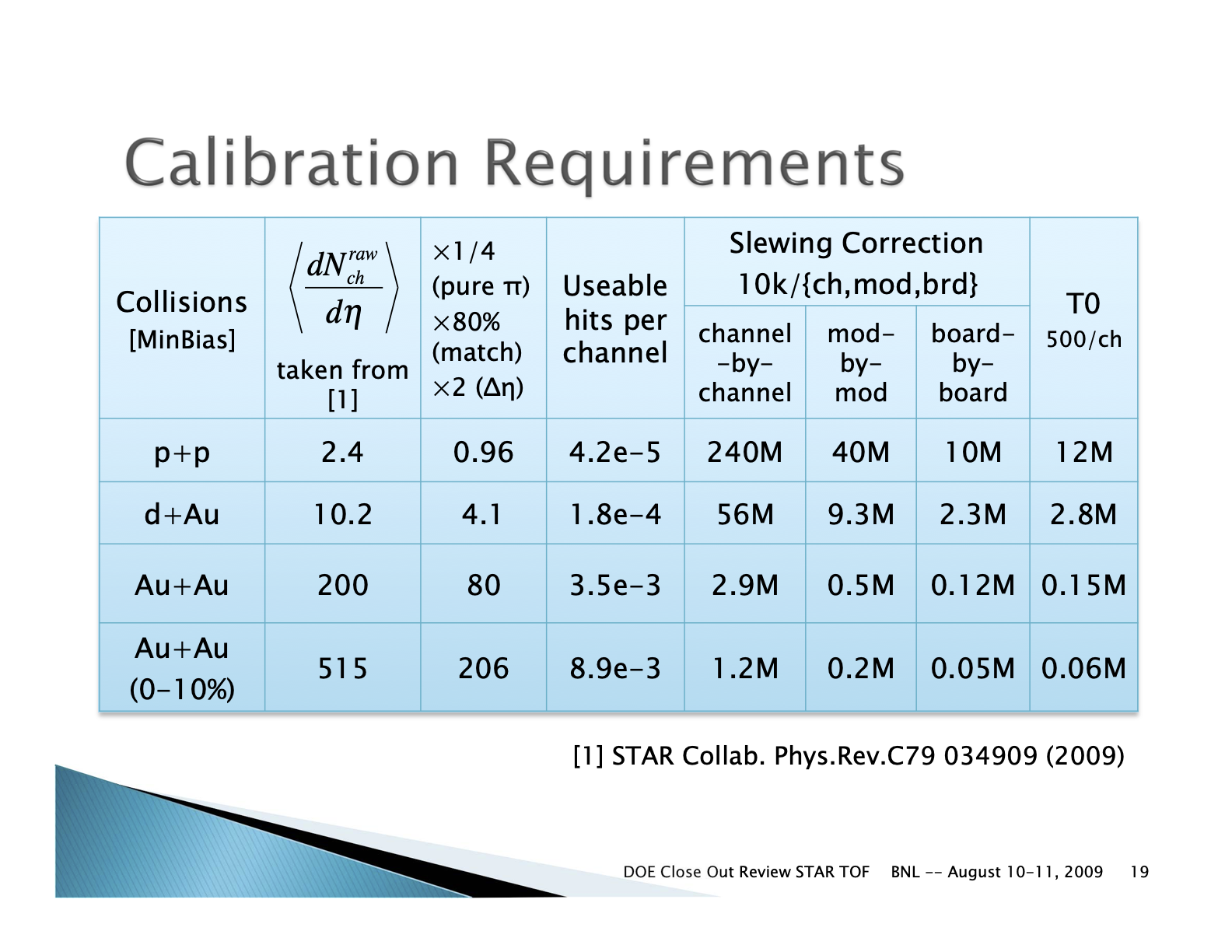
Links to several older calibration details with historical data
- Data sets from Runs 9 - 12
- Data sets from Runs 12 - 18
- Daniel Brandenburg: http://www4.rcf.bnl.gov/~jdb/tofCalibration/
Run 8 - 10 time resolutions
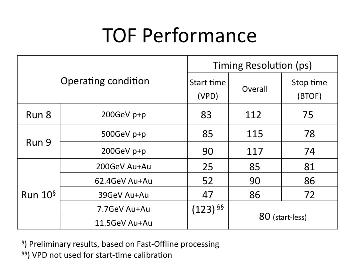
TOF MRPC Prototype resolutions
.jpg)
Run 10 - 200 GeV Calibrations
Run 10 Calibrations
Run 10 200 GeV FF
[This a test page for now. Soon to be edited.]
The calibration began with ntuples generated from a preproduction:
  /star/data57/reco/AuAu200_production/FullField/P10ih_calib1/2010/*/*

    log files on /star/rcf/prodlog/P10ih_calib1/log/daq
The ntuples can be found:
28 files (61810 events):
/star/data05/scratch/rderradi/run10/TofCalib/ntuples/200GeV_1/out/

316 files (2398210 events):
/star/data05/scratch/rderradi/run10/TofCalib/ntuples/200GeV_2/out/

77 files (497944 events) - not properly closed:
/star/data05/scratch/rderradi/run10/TofCalib/ntuples/200GeV_3/out/
The 77 files not properly closed were merged with hadd to properly close them.
Then the ntuples were used for the start side(vpd) calibration. The code package used for this is attached and can be found here:
To run the start side calibration: ./doCalib filelist traynumber
Tray number for start side can be any tray number, I recommend 0. Start side calibration used a 20% outlier cut. This can be selected in doCalib.cpp and changing the value pCut =0.20.
The outlier removes the upper 20% of slowest hits--highest leading edge times.
Produced from the start side calibration is pvpdCali.dat and pvpdCali.root. These files are used to shift the vpdvz offset between the east and west vpd, and ultimately, the vpd's calibration parameters that are loaded into the database. To shift the offset, perform a Gaussian fit to VzCorr2->ProjectionY() and take that mean value. This is the VzOffset. Apply it to the convertVpd.C macro (http://drupal.star.bnl.gov/STAR/system/files/convertVpd.tar_.gz) on the line: 2454.21696153-VzOffset. This macro generates pvpdCali_4DB.dat. These are the parameters loaded into the database.
Now apply the shift to pvpdCali.root so that T0's are properly corrected for the stop side(TOF) calibration. This is done with the code in this package:
To run the code: use ./doCalib filelist traynumber . The traynumber does not matter, use 0 again. Be sure this is the same file list as before and that the generated pvpdCali.root and pvpdCali_4DB.dat files are in the same directory. This way the VzOffset is applied. An updated pvpdCali.root is produced.
Typically, the pvpdCali.root is then used in the stop side calibration. But because we are doing a cell based calibration, we wanted to increase statistics. This caused an increase in IO from disk and delayed calibration since data for all trays is cycled over regardless of which tray is being calibrated. To get around this, we used a splitting macro that reads in the ntuples and pvpdCali.root, and then it splits the ntuples into TDIG based files with the startside information stored with it. The splitting macro is attached to this page here:
The board based ntuples are then used to calibrate on a cell level for each board. This is done with this code package:
To run it: ./doCalib filelist traynumber boardnumber. Here tray number is 0-119 and board number is 0-959. It is important that the proper board is selected from the given tray number. For example tray 0 has boards 0-7, tray 1 has boards 8-15 and so on.
Produced among other files are tray_$tray#_board_$board#_$iteration#.dat files. These files are added together for all trays and create the parameter files used for the database. To add them together, the macros addZtdig.C, addT0Ttdig.C, and addt0tig.C were used(http://drupal.star.bnl.gov/STAR/system/files/addstopsidemacros.tar_.gz) and generated zCali_4DB.dat, totCali_4DB.dat, and t0_4DB.dat respectively.
To check the produced calibration parameters, use a check macro that reads in matchmaker produced ntuples and applies the parameters (http://drupal.star.bnl.gov/STAR/system/files/simpleQAmacro.tar_.gz). The result is a .root file that can be used QA checking. The macro needs to be edited to find the proper parameters and the proper name for an output file. It works with './checknew filelist_location' In addition, there are other methods for QA checking.
The calibration was performed over:
Run #        -events
>
> 11004071   -623835
> 11009017   -497717
> 11015019   -499030
> 11020023   -500001
> 11026034   -500001
> 11035026   -699977
>
> total:3320561 events.
---Issues that came up during the calibration procedure---
First off is the outlier rejection. Not inserting the outlier rejection in all stages of the start side calibration caused issues. This was seen when shifting the T0s for the stopside calibration and in comparing different QA checking macros. This can lead to 40ps differences in the time. Also, there is a slight difference in the way the outlier is handled in the calibration procedure versus the vpdcalibmaker. This difference of T0s averages out over events to be on the order of 2-3 ps. We kept this difference in place for 200, because this method used in the production of 39 earlier in the year.
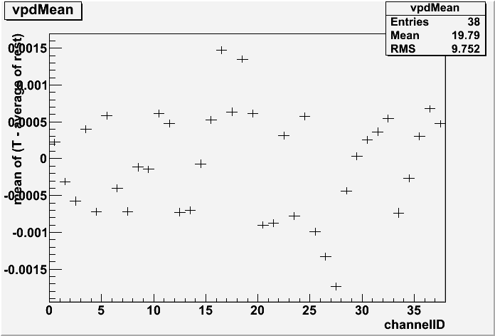
Other differences include the selection criteria for events. Needed to replace dcaZ with vertexZ since in heavy ion the primary vertex is filled and more reliable(dcaZ was used in pp where the primary vertex was not always filled). Same with dcaX and dcaY to vertexX and vertexY respectively. Also dropped the if(sqrt(pow(tofr->vertexX,2)+pow(tofr->vertexY,2))>rCut) cut. This is because by selecting a primary vertex with vertexZ, this should have already been applied in order to be a primary vertex.
Another minor one was in the QA macro calculating the vpdMean. Turns out it was being handled incorrectly, but okay now. Originally it looked like (bad structure):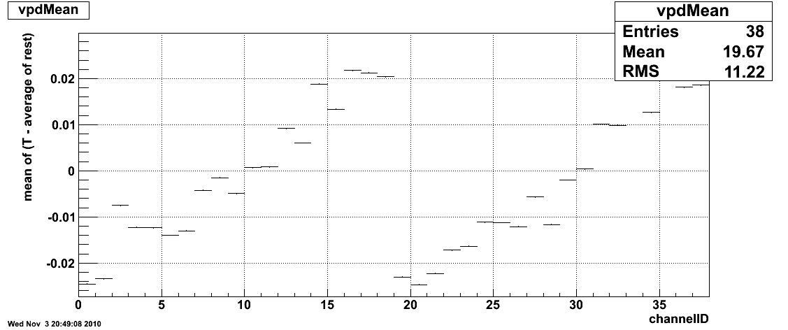
And with the fix, it became:
Run 10 200GeV RFF
Place holder. Two samples used.
Run 11 - 19 GeV Calibration
Place holder. Board+cell based calibration.
Run 11 - 62 GeV Calibration
Place holder. 40ns.
Run 18 Calibrations
Isobar Calibrations
- Calibration QA (Zaochen Ye's blog)
- VPD calibration
- BTOF-TPC alignment: Zlocal, Ylocal
- BTOF cell-by-cell calibration
27 GeV Calibrations
First Half ( days - 141)
- VPD Calibration QA
- BTOF alignment
- BTOF T0
Second Half (days 142-168)
- VPD calibration QA
- BTOF alignment
- BTOF T0
- Comments:
- BTOF slewing and Local-Z re-used from past full calibration (Run16)
- calalgo=1 (startless mode, VPD is not used for the BTOF start time)
Fixed Target Calibrations
Run 19 Calibrations
Run 19 Calibrations
19.6 GeV Calibrations
- VPD Calibration QA
- BTOF alignment
- xqa
- yqa
- BTOF T0
- SummaryQA
- Comments:
- BTOF slewing and Local-Z re-used from past full calibration (Run16)
- calalgo=1 (startless mode, VPD is not used for the BTOF start time)
19.6 GeV Calibrations with new TPC alignment
- VPD Calibration QA
- BTOF alignment
- xqa
- yqa
- BTOF T0
- SummaryQA
- Comments: Charged particle mass splitting is observed.
Fixed Target Calibrations
- xqa
- yqa
- SummaryQA
200 GeV Calibrations
- VPD Calibration QA
- BTOF alignment
- xqa
- yqa
- BTOF T0
- SummaryQA
4p59/3p85 GeV Calibrations with new TPC alignment
- Startless mode
- BTOF alignment
- xqa
- yqa
- BTOF T0
- SummaryQA
Run 20 Calibrations
Run 20 Calibrations
- BTOF Data Windows for Run 20 (Zaochen's blog)
BToF time resolution for Startless mode is around 0.06ns and is 0.14ns (11.5GeV), 0.16ns(9.2GeV) for Vpdstart mode.
Run20 FXT Calibrations: 5p75/7p3/9p8 GeV
- Startless mode
- BTOF alignment
- xqa
- yqa
- BTOF T0
- SummaryQA
- xqa
- yqa
- SummaryQA
11.5 GeV Calibrations
- VPD Calibration QA
- BTOF alignment
- xqa
- yqa
- BTOF T0
- SummaryQA
9.2 GeV Calibrations
- VPD Calibration QA
- BTOF alignment
- xqa
- yqa
- BTOF T0
- SummaryQA
Run 21 Calibrations
Run21 Calibrations
AuAu 7.7 GeV Calibrations
- VPD Calibration QA
- BTOF alignment
- xqa
- yqa
- BTOF T0
- SummaryQA
OO 200GeV Calibrations
- VPD Calibration QA
- BTOF alignment
- xqa
- yqa
- BTOF T0
- SummaryQA
- charged particle mass splitting for FF data
AuAu 17.3 GeV Calibrations
- VPD Calibration QA
- BTOF alignment
- xqa
- yqa
- BTOF T0
- SummaryQA
dAu 200 GeV Calibrations
- VPD Calibration QA
- BTOF alignment
- xqa
- yqa
- BTOF T0
- SummaryQA
- asymmetry in VpdVz-TPCVz plot
AuAu FXT Calibrations (3.85GeV, 26.5GeV, 44.5GeV, 70GeV, 100GeV)
- Using Run21 17.3GeV parameter tables
- BTOF T0
- SummaryQA
TOF/VPD Calibration How-To's
Trigger Window Determination
Here is documentation on how to determine the trigger windows for ToFs 120 trays and the 2 start detectors.
I determined the trigger windows on run 13037090. To do this, I used StRoot.tar.gz and extracted it to my work directory. Then changed directory to StRoot/RTS/src/RTS_EXAMPLE and ran Rts_Example.sh. This creates the executable rts_example from rts_example.C. Both Rts_Example.sh and rts_example.C have been customized from the typical StRoot version to translate information given in a .daq file into a useful .root file. To run rts_example, I use run_test.csh. This is essentially:
starver SL11e
rts_example -o tof_13037090.root -D tof inputfilepath/st_physics_13037090_raw_1010001.daq
where tof_run#.root is your output file and .daq is your input file.
Then the trigger windows are determined from the .root file by running over it with plot_trgwindow.C.
To do this:
root
.x plot_trgwindow.C("run#");
run number is important because this is how the script knows to read in tof_run#.root.
Produced is a .dat file that lists the high and low limits for each tray's trigger window and a postscript that shows the new limits in blue for each tray and if defined inside plot_trgwindow.C, red lines for the old trigger window limits(testrun11.dat in this example).
Attached to this page is the StRoot.tar.gz package, run_test.csh, plot_trgwindow.C, old trigger window limits, new trigger window limits, and a postscript displaying the limits on top of the data. (I put them in zip containers due to the file attachment restrictions.)
VPD Slewing corrections for bbq & mxq
1. Acquiring VPD gain setting data
At the sc5.starp station, there are two GUIs on the upVPD monitor:
"large GUI" shows all the channel values, and where one powers them on/off...
"small GUI" selects between different gain sets A, B, C, & default...
start with the VPD HV **off**
once there is a decent non-VPD-based trigger and stable beam:
1. on small GUI, click "! upVPD HV A" button
2. on large GUI, click in lower left corner to power on upVPD HV
3. wait until all channels are "green" (~20 sec).
4. make sure the values (upper left corner of large GUI,
leftmost column) are as expected
5. wait ~1min for PMTs to settle (or take some other test run)
6. start run: TRG+DAQ+TOF only, 300k events.
use string "upVPD HV A" in the shiftlog entry
7. power off HV (large GUI lower left corner)
8. wait until channels reach 0 (~20 sec)
9. on small GUI, click "! upVPD HV B" button
10. on large GUI, click in lower left corner to power on upVPD HV
11. wait until all channels are "green" (~20 sec).
12. make sure the values (upper left corner of large GUI,
leftmost column) are as expected
13. wait ~1min for PMTs to settle (or take some other test run)
14. start run: TRG+DAQ+TOF only, 300k events.
use string "upVPD HV B" in the shiftlog entry
15. power off HV (large GUI lower left corner)
16. on small GUI, click "! upVPD HV C" button
17. on large GUI, click in lower left corner to power on upVPD HV
18. wait until all channels are "green" (~20 sec).
19. make sure the values (upper left corner of large GUI,
leftmost column) are as expected
20. wait ~1min for PMTs to settle (or take some other test run)
21. start run: TRG+DAQ+TOF only, 300k events.
use string "upVPD HV C" in the shiftlog entry
22. power off HV (large GUI lower left corner)
23. on small GUI, click "! DEFAULT" button.
24. power on the VPD HV.
Do not use the small GUI anymore. In fact, feel free to close it!
At this point, I will get the data from HPSS, calculate the new gains, and then upload them to sc5.
2. Calculate VPD Gains
0=beam, save trigger detector info, no trees...
1=noise, save TOF/MTD hits trees, no coarse counter cut...
2=beam, save **MTD** hits trees, w/ coarse counter cut...
3=beam, no coarse counter cut for trigger time plots (TOF&MTD)...
..... online::online kRunUse = 16039019
Error in <TTree::SetBranchAddress>: unknown branch -> p2p_sin
..... online::loop Opening online_16039019.root
0x866d270
..... online::loop Nentries = 300000
- Make sure that the VPD HV is **OFF** before uploading - otherwise the HV values will not be set properly.
- autoload location : sc5.starp.bnl.gov:/home/sysuser/epics3.13.10/Application/BBCApp/config/upVPD/upVPD.save
3. Collect data for VPD Slewing corrections
1. Data should be taken using a VPD based trigger
2. For AuAu collisions ~ 100K minimum events are needed
3. For pp200 ~200K events were needed
4. As soon as the data is acquired (or even before ) make arrangments with Lidia for the fast offline production to be started. It needs to start immediately
4. Perform VPD Slewing corrections for bbq & mxq crates
1. Plot the TAC{East} - TAC{West} + 4096 vs. TPC vz to determine the TAC to ps conversion factor. Bbq and Mxq are not neccessarily the same - so check both.
2. Create calibration tuples from MuDsts - these contain just the VPD data, TPC z vertex etc. that we need.
Current tuple maker is at : /star/institutions/rice/jdb/calib/ntupler/
3. Setup a config file for slewing corrections - set data uri, bbq or mxq datasource and output filenames for qa and parameters
4. Run the slewing jobs
5. Check the QA and if there is time before uploading have Shuai check the resolution.
6. Upload parameter files to startrg.starp.bnl.gov in the ~staruser/ location with names like (m)vpd_slew_corr.<date>.txt for bbq (mxq)
7. check the md5sums of the two files you just made and compare them to the original parameter files - sometimes the line-endings get scrambled
7. Make a soft link from (m)vpd_slew_corr.<date>.txt to (m)vpd_slew_corr.txt for bbq (mxq).
8. Have Jack run the script to write slewing corrections to crates.
5. Check VPD plots - if everything looks good then you are done
QA from run15 pA200 is attached for the full statistics runs
BTOF Offline Reconstruction
BTOF Offline Reconstruction
Known/solved issues:
- P18ih (Run 9 pp500): TpcRefSys issue keeps BTOF geometry from getting correctly set up
- this affects all runs before 2013 (see StBTofGeometry.cxx)
- fixed in SL19d library
- quick fix: run BTOF afterburner on MuDSTs to recreate BTOF matching and calibrations
- SL17h/SL17i: Optimized libraries missing west BTOF geometry.
PPV with the use of BTOF
This area contains the study on the Pileup-Proof Vertex (PPV) finder with the use of hits from Barrel Time-Of-Flight (BTOF).
Coding
Checklist:
This list the items that need to be implemted or QAed to include BTOF information in the PPV.
Coding: - almost done, need review by experts
1) BTOF hits (StBTofHitMaker) to be loaded before PPV - done
2) BTOF geometry need to be initialized for the PPV - done
As PPV is executed before the StBTofMatchMaker, I think in the future, the BTOF geometry will be firstly initialized in PPV in the chain and added to the memory. StBTofMatchMaker will then load this directly w/o creating its own BTof geometry.
3) Creation of BtofHitList - done
The BTOF part is rather segmented accroding to tray/module/cell, but BTOF modules don't have the same deta coverage. The binning is segmented according to module numbers.
The justification of match and veto is different from other sub-systems as we now allow one track to project onto multiple modules considering the Vz spread and track curvature.
Define: Match - any of these projected modules has a valid BTOF hit. Veto - At least one projected module is active and none of the active projected modules has a valid BTOF hit.
4) Update on TrackData VertexData to include BTOF variables - done
5) Main matching function: matchTrack2BTOF(...) - done
Currently, the match/veto is done at the module level. I set a localZ cut (|z|<3cm currently and also possibly remove cell 1 and 6 to require the track pointing to the center of the module). But this can be tuned in the future. Also whether we need to to match at the cell level can also be discussed.
6) Update on StEvent/StPrimaryVertex, add mNumMatchesWithBTOF - done (need update in CVS)
7) A switch to decide whether to use BTOF or not. - done (but need to add an additional bfc option)
The lastest version is located in /star/u/dongx/lbl/tof/NewEvent/Run9/PPV/StRoot
QA: - ongoing
MC simulation study
Default PPV for PYTHIA minibias events in y2009
The first check is to test the default PPV and check whether the result is consitent with those from Vertex-Group experts.
GSTAR setup
geometry y2009
BTOF geometry setup: btofConfig = 12 (Run 9 with 94 trays)
vsig 0.01 60.0
gkine -1 0 0 100 -6.3 6.3 0 6.29 -100.0 100.0
PYTHIA setup
MSEL 1 ! Collision type
MSTP (51)=7
MSTP (82)=4
PARP (82)=2.0
PARP (83)=0.5
PARP (84)=0.4
PARP (85)=0.9
PARP (86)=0.95
PARP (89)=1800
PARP (90)=0.25
PARP (91)=1.0
PARP (67)=4.0
BFC chain reconstruction options
trs fss y2009 Idst IAna l0 tpcI fcf ftpc Tree logger ITTF Sti VFPPV NoSvtIt NoSsdIt bbcSim tofsim tags emcY2 EEfs evout -dstout IdTruth geantout big fzin MiniMcMk eemcDb beamLine clearmem
Just for record about the PPV cuts:
StGenericVertexMaker:INFO - PPV::cuts
MinFitPfrac=nFit/nPos =0.7
MaxTrkDcaRxy/cm=3
MinTrkPt GeV/c =0.2
MinMatchTr of prim tracks =2
MaxZrange (cm)for glob tracks =200
MaxZradius (cm) for prim tracks &Likelihood =3
MinAdcBemc for MIP =8
MinAdcEemc for MIP =5
bool isMC =1
bool useCtb =1
bool DropPostCrossingTrack =1
Store # of UnqualifiedVertex =5
Store=1 oneTrack-vertex if track PT/GeV>10
dump tracks for beamLine study =0
Results
Total 999 events PYTHIA mb events were processed. Among these, 990 events have at least one reconstructed vertex (frac = 99.1 +/- 0.3 %). The following plot shows the "funnyR" plot of the vertex ranking for all found vertices.

Clearly seen is there are lots of vertices with negative ranking. If we define the vertices with positive ranking are "good" vertices, the left plot in the following shows the "good" vertex statistics
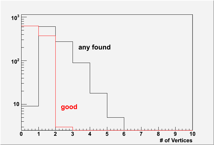
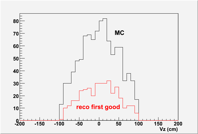

Only 376 events (frac 37.6 +/- 1.5 %) have at least one "good" vertex. The middle plot shows the Vz distributions for MC input and the reconstructed first "good" vertices. However, if you look at the right plot which shows the Vz difference between reconstructed vertex and the MC input vertex, not only all good vertices are well distributed, most of any-found vertices even with negative ranking are within 1cm difference.
If we define the "good" vertex is |Vz(rec)-Vz(MC)|<1cm, as Jan Balewski studied in this page: http://www.star.bnl.gov/protected/spin/balewski/2005-PPV-vertex/effiMC/ then 962 events (frac 96.3 +/- 0.6 %) have at least one "good" vertex.
One note about the bfc log, I notice there is a message as the following:
......
BTOW status tables questionable,
PPV results qauestionable,
F I X B T O W S T A T U S T A B L E S B E F O R E U S E !!
chain will continue taking whatever is loaded in to DB
Jan Balewski, January 2006
......
The full log file is /star/u/dongx/institutions/tof/simulator/simu_PPV/code/default/test.log
Update 9/10/2009
With including BTOF in the PPV, please find the vertex ranking distributions below. (Note: only 94 trays in y2009)

The # of events containing at least one vertex with ranking>0 is 584 (frac. 58.5 +/- 1.6 %). This number is more close to what I have in mind the vertex finding efficiency for pp minibias events. So the early low efficiency was due to missing CTB, while BTOF now is acting like CTB ???
Update 9/22/2009
After several rounds of message exchange with Jan, Rosi etc, I found several places that can be improved.
1) Usually we use the BBC triggered MB events for study. So in the following analysis, I also only select the BBC triggered MB events for the vertex efficiency study. To select BBC triggered events, please refer to the code $STAR/StRoot/StTriggerUtilities/Bbc on how to implement it.
2) Use ideal ped/gain/status for BEMC in the simulation instead of the pars for real data. To turn on this, one need to modify the bfc.C file: add the following lines for the db maker in the bfc.C (after line 123)
dbMk->SetFlavor("sim","bemcPed"); // set all ped=0 <==THIS
dbMk->SetFlavor("sim","bemcStatus"); // ideal, all=on
dbMk->SetFlavor("sim","bemcCalib"); // use ideal gains
These two changes significantly improves the final vertex efficiency (I will show later). The following two are also suggested, although the impact is marginal.
3) Similarly use ideal ped/gain/status for EEMC.
dbMk->SetFlavor("sim","eemcDbPMTped");
dbMk->SetFlavor("sim","eemcDbPMTstat");
dbMk->SetFlavor("sim","eemcDbPMTcal");
4) Use ideal TPC RDO mask. You can find an example here: /star/u/dongx/institutions/tof/simulator/simu_PPV/test/StarDb/RunLog/onl/tpcRDOMasks.y2009.C
With these updates included, the following plot shows the # of good vertex distribution from 500 PYTHIA mb events test.

The vertex efficiency is now raised to ~50%. (OK? low?)
Just as a check on the BBC efficiency, here I accepted 418 events with BBC triggers out of 500 events in total. Eff = 83.6 +/- 1.7 %, which is reasonable.
MC study on PPV with BTOF in Run 9 geometry
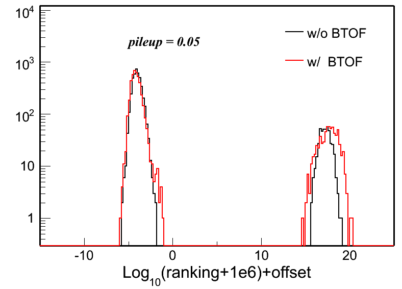
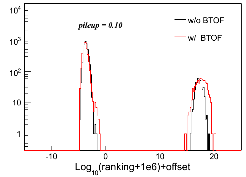
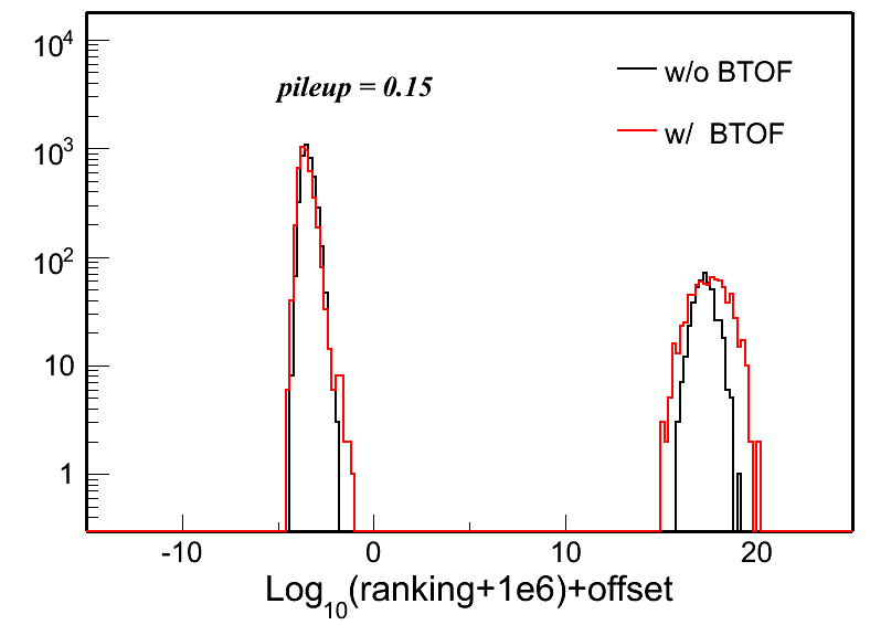
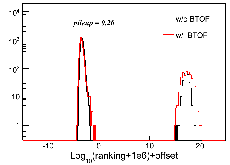
This MC simulation study is to illustrate the performance of PPV vertex finder with BTOF added under different pileup assumptions. All the PPV coding parts with BTOF included are updated in this page.
The geometry used here is y2009 geometry (with 94 BTOF trays). Generator used is PYTHIA with CDF "TuneA" setting. The details of gstar setup and reconstruction chain can be found here. The default PPV efficiency for this setup (with BBC trigger selection) is ~45-50%.
The triggered event selected are BBC triggered minibias events. The simulation has included the TPC pileup minibias events for several different pileup conditions. The pileup simulation procedure is well described in Jan Balewski's web page. I choose the following pileup setup:
mode BTOF back 1; mode TPCE back 3761376; gback 470 470 0.15 106. 1.5; rndm 10 1200
A few explanations:
- 'mode BTOF back 1' means try pileup for BTOF only in the same bXing
- '3761376' means for TPC try pileup for 376 bXing before , in, and after trigger event. TRS is set up to handle pileup correctly. Note, 376*107=40 musec - the TPC drift time.
- gback is deciding how pileup events will be pooled from your minb.fzd file.
- '470' is # of tried bXIngs back & forward in time.
- 0.15 is average # of added events for given bXIng, drawn with Poisson distribution - multiple interactions for the same bXing may happen if prob is large. I choose this number to be 0.0001, 0.02, 0.05, 0.10, 0.15, 0.20, 0.30, 0.40, 0.50 for different pileup levels.
- 106. is time interval , multiplied by bXIng offset and presented to the peilup-enabled slow simulators, so the code know how much in time analog signal needs to be shifted and in which direction.
- 1.5 if averaged # of skipped events in minb.fzd file. Once file is exhausted it reopens it again. If you skip too few soon your pileup events start to repeat. If you skip too much you read inpute file like creazy
- 'rndm' is probably seed for pileup random pileup generator
Here shows the results:
- Vertex efficiency
Fig. 1: Vertex efficiencies in different pileup levels for cases of w/ BTOF and w/o BTOF.
.gif)
Here: good vertex is definited as vertex with positiving ranking. real vertex is definited as good vertex && |Vz-Vz_MC|<1 cm.
- # of BTOF/BEMC Matches
Fig. 2: # of BTOF/BEMC matches for the first good & real vertex in different pileup levels.
.gif)
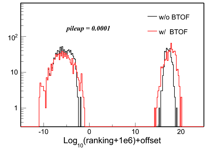
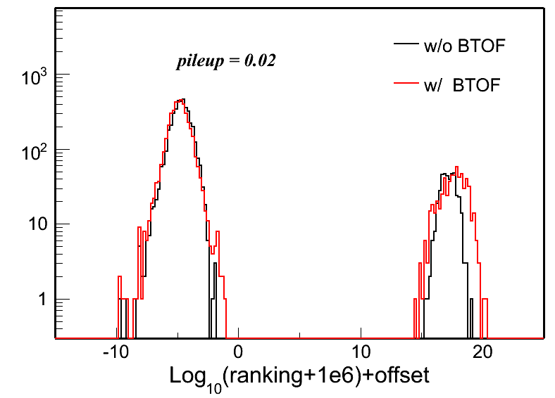
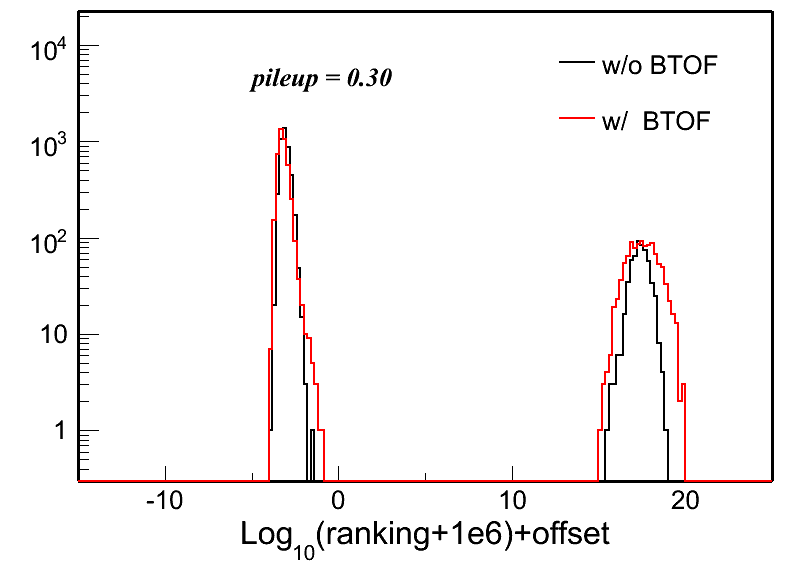
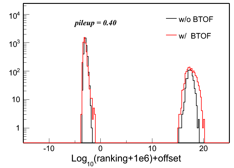
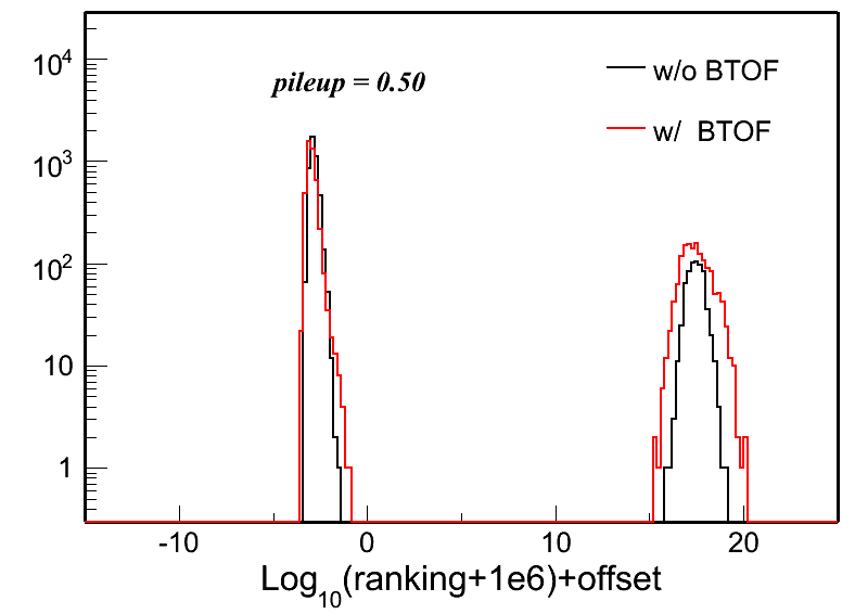
- Ranking distributions
Fig. 3: Vertex ranking distributions in each pileup level for both w/ and w/o BTOF cases.
 |
 |
 |
 |
 |
 |
 |
 |
 |
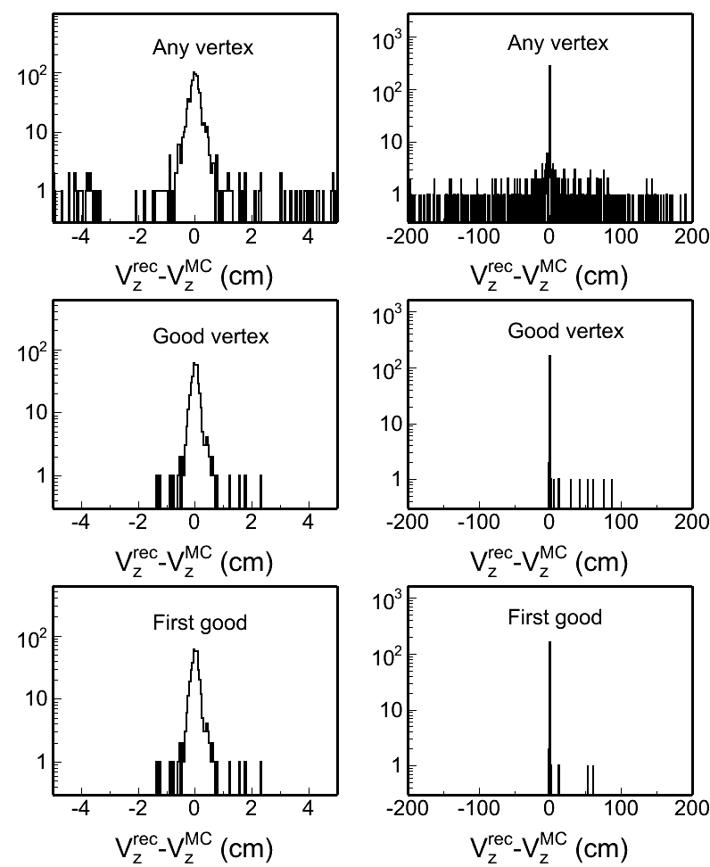
- Vertex z difference
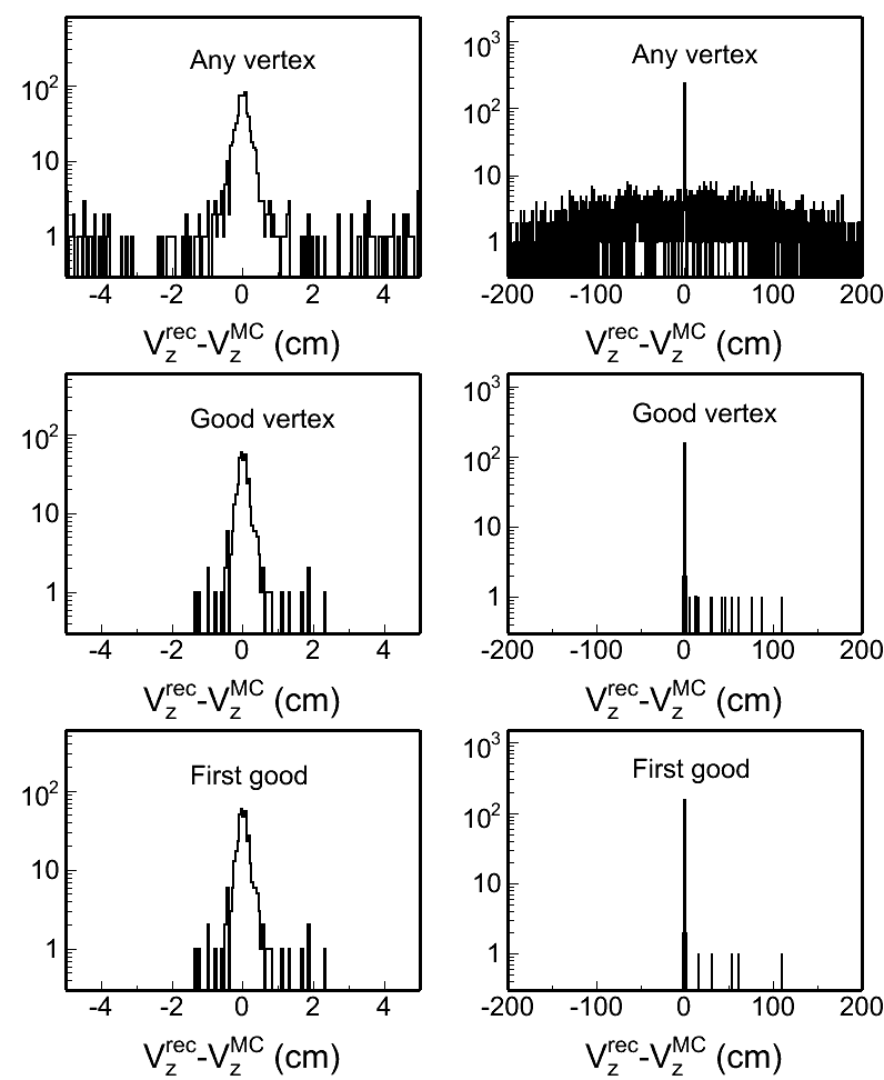
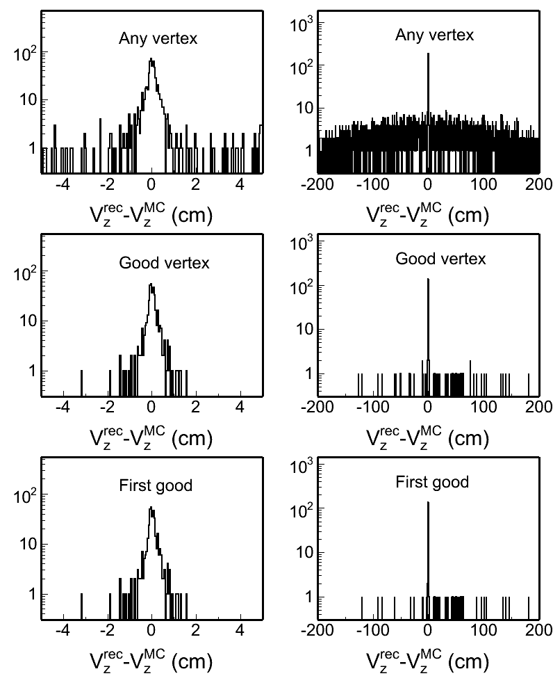
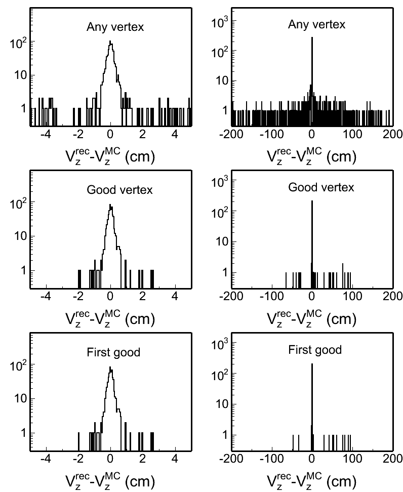
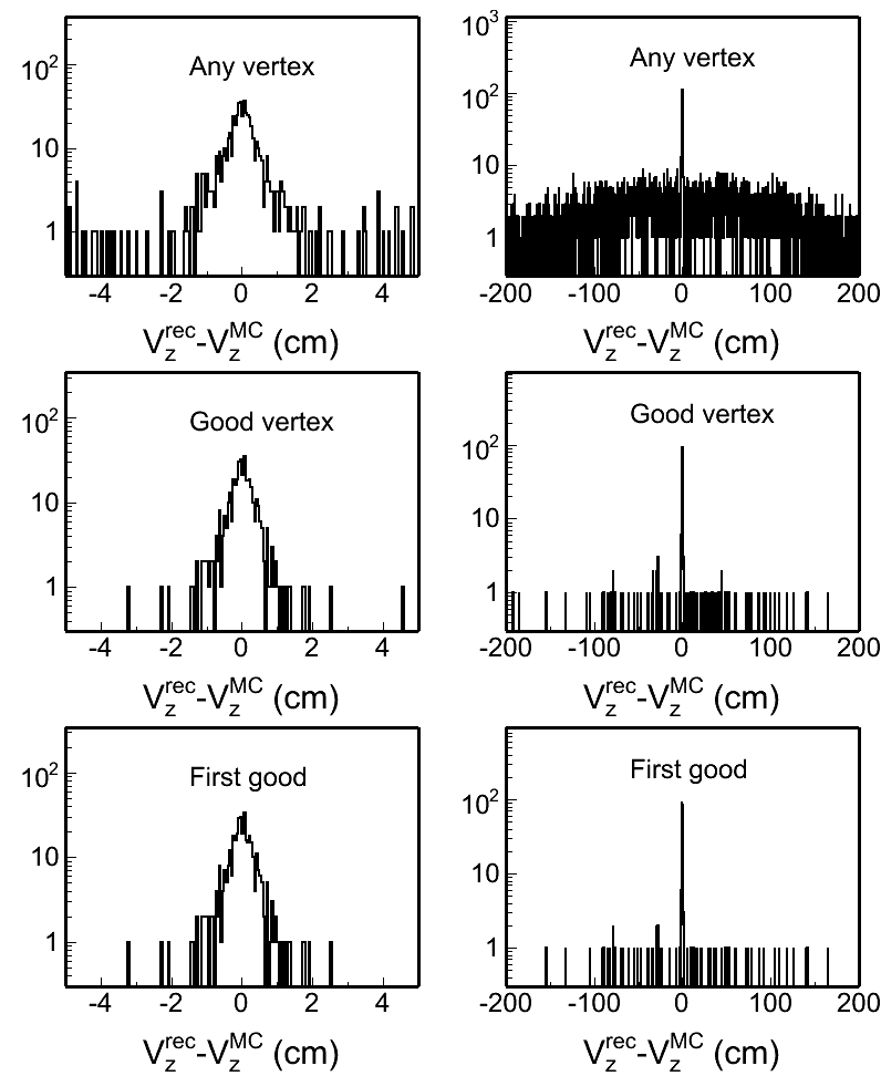
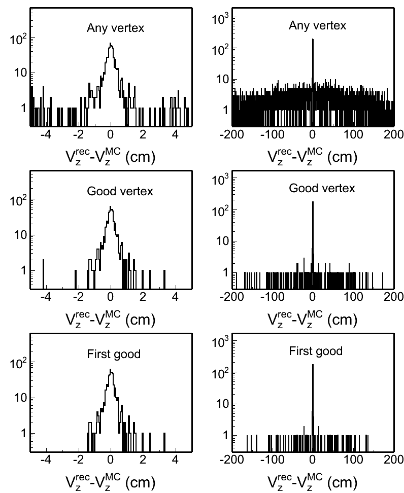
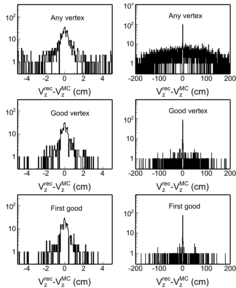
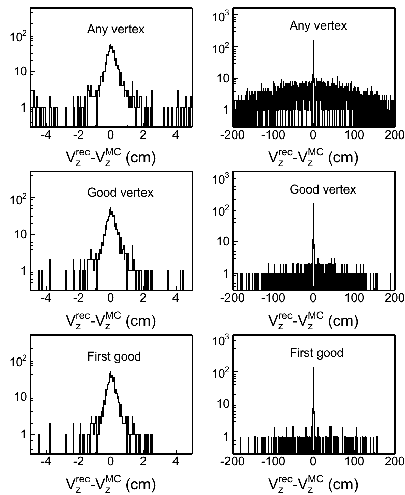
Fig. 4: Vertex z difference (Vzrec - VzMC) distributions in different pileup levels for both w/ and w/o BTOF cases. Two plots in each row in each plot are the same distribution, but shown in two different ranges.
| pileup = 0.0001 | pileup = 0.02 | pileup = 0.05 | |
|
w/o BTOF |
 |
 |
 |
|
w/ BTOF |
 |
 |
 |
| pileup = 0.10 | pileup = 0.15 | pileup = 0.20 | |
| w/o BTOF | 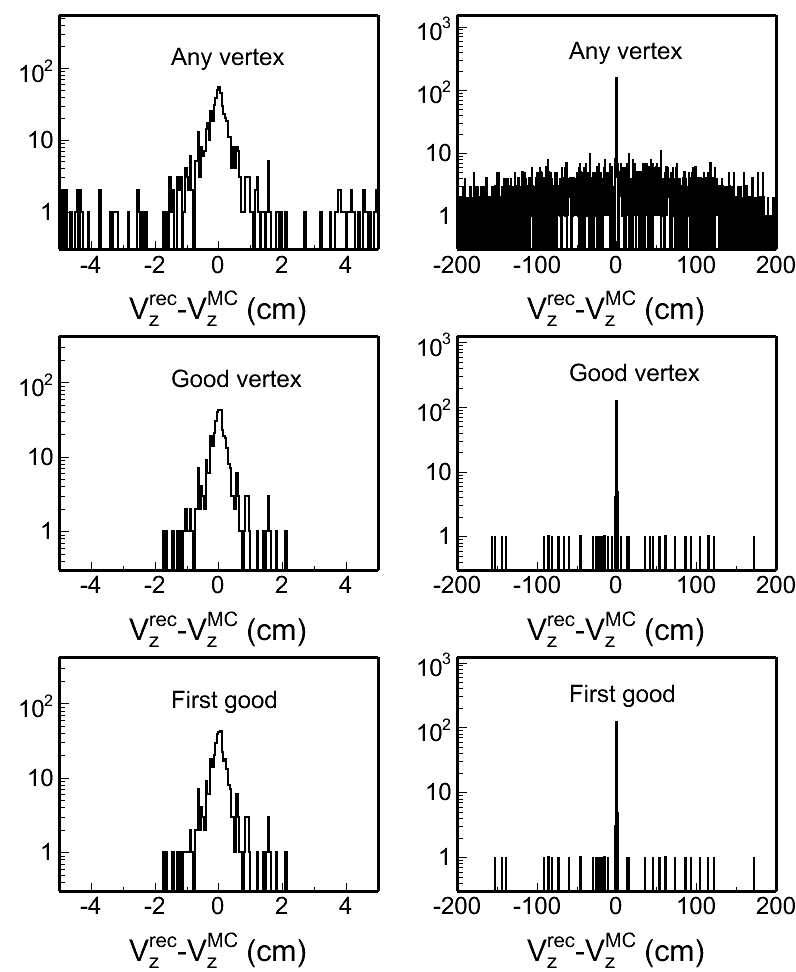 |
 |
 |
|
w/ BTOF |
 |
 |
 |
| pileup = 0.30 | pileup = 0.40 | pileup = 0.50 | |
|
w/o BTOF |
 |
 |
 |
|
w/ BTOF |
 |
 |
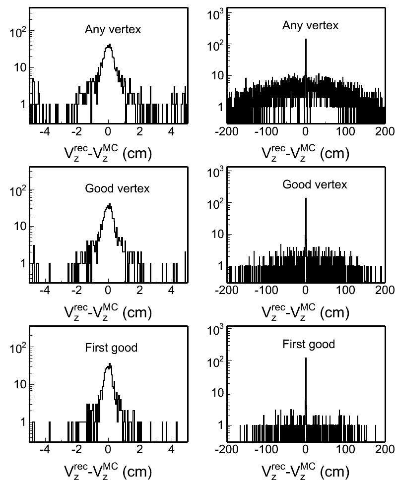 |
To quantify these distributions, I use the following two variables: Gaussian width of the main peak around 0 and the RMS of the whole distribution. Fig. 5 and 6 show the distributions of these two:
Fig. 5: Peak width of Vzrec-VzMC in Fig. 4 in different pileup levels.
.gif)
Fig. 6: RMS of Vzrec-VzMC distributions in different pileup levels.
.gif)
- CPU time
The CPU time in processing pileup simulation grows rapidly as the pileup level increases. Fig. 7 shows the CPU time needed per event as a function of pileup level. The time shown here is the averaged time for 1000 events splitted into 10 jobs executed on RCF nodes. I see there is a couple out of these 10 jobs took significantly shorter time than others, and I guess this is due to the performance on different node. But I haven't confirmed it yet.
Fig. 7: CPU time vs pielup levels
.gif)
Update on 12/23/2009
There were some questions raised at the S&C meeting about why the resolution w/ TOF degrades at low pileup cases. However, as we know, including BTOF would increase the fraction of these events finding a good vertex. While this improvement is mainly on those events with fewer # of EMC matches that will not be reconstructed with one good vertex if BTOF is not included (see the attached plot for the comparison between w/ and w/o BTOF at 0.0001 pileup level). Events entering into Fig. 5 are any of those who has at least one good vertex. In the case of w/ BTOF, many events with only 1 or 0 EMCs matches can have one reconstructed vertex because of BTOF matches included. While tracks with small pT can reach BTOF easier than BEMC. So one would expect the mean pT of the tracks from these good vertices if we include BTOF would be smaller (not sure how big quantitatively), then resulting in worse projection uncertainty to the beamline, thus these event sample will have slight worse Vz resolution.
I don't have a better idea to pick up the same event sample in the case of w/ BTOF as that in the case of w/o BTOF rather than I select the number of BEMC matches >=2 for the vertices that will be filled in my new Vz difference plot. Fig. 8 shows the same distribution as that in Fig. 5 but with nBEMCMatch>=2.
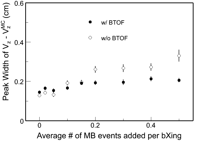
One can see the change is in the right direction, but still it seems not perfect from this plot for very low pileup cases. I also went back to compare the reconstructed vertices event-by-event, here are some output files:
/star/u/dongx/lbl/tof/simulator/simu_PPV/ana/woTOF_0.0001.log and wTOF_0.0001.log
The results are very similar except a couple of 0.1cm movements in some events (I attribute this to the PPV step size). Furthermore, in the new peak width plot I show here, for these very low pileup cases, the difference between two are even much smaller 0.1cm, which I expect to be the step size in the PPV.
Test with real data
The PPV with BTOF included is then tested with Run 9 real data. The detail of the coding explanation can be found here.
The PPV is tested for two cases: w/ BTOF and w/o BTOF and then I make comparisions later. The data files used in this test are (1862 events in total):
st_physics_10085140_raw_2020001.daq
st_physics_10096026_raw_1020001.daq
(Note that in 500 GeV runs, many of the triggered events are HT or JP, presumably with higher multiplicity compared with MB triggers.) And the chain options used in the production are:
pp2009a ITTF BEmcChkStat QAalltrigs btofDat Corr3 OSpaceZ2 OGridLeak3D beamLine -VFMinuit VFPPVnoCTB -dstout -evout
Production was done using the DEV lib on 11/05/2009. Here shows the results:
Fig. 1: The 2-D correlation plot of # of good vertices in each event for PPV w/ TOF and w/o TOF.
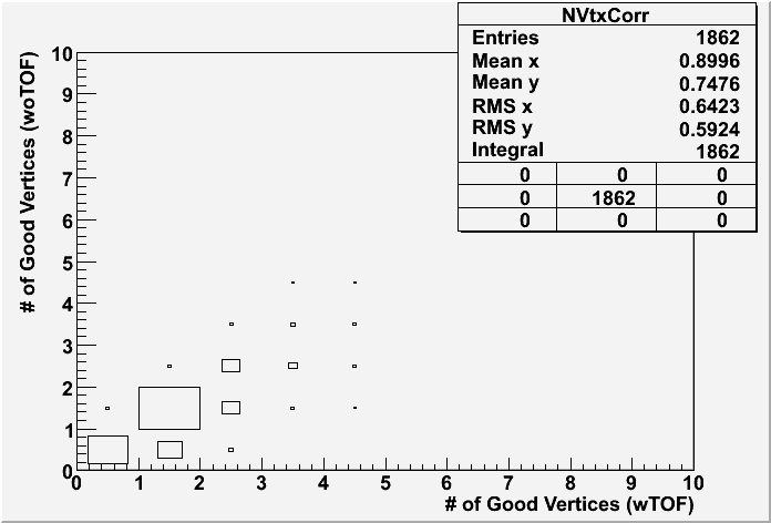
Fig. 2: The ranking distributions for all vertices from PPV w/ and w/o TOF
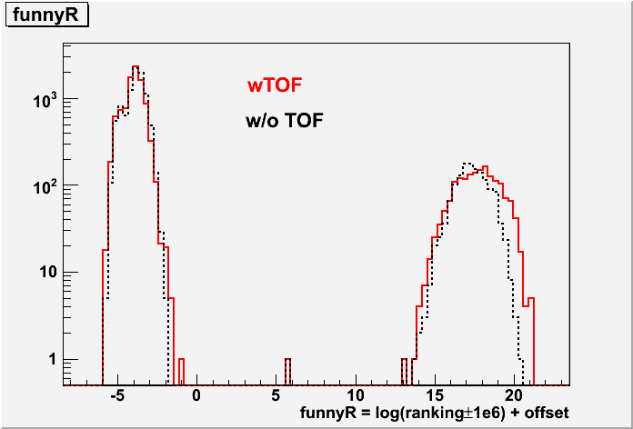
Fig. 3: Vz correlation for the good vertex (ranking>0) with the highest ranking in each event for PPV w/ and w/o TOF. Note that, if the event doesn't have any good vertex, the Vz is set to be -999 in my calculation, which appears in the underflow in the histogram statstics.

Fig. 4: Vz difference between vertices found in PPV w/ TOF and w/o TOF for the first good vertex in each event if any. The 0.1 cm step seems to come from the PPV.

Update on 4/5/2010:
I have also run some test with the 200 GeV real data. The test has been carried out on the following daq file
st_physics_10124075_raw_1030001.MuDst.root
All the rest setup are the same as described above. Here are the test results:
Fig. 5: The 2-D correlation plot of # of good vertices in each event for PPV w/ TOF and w/o TOF (200 GeV)
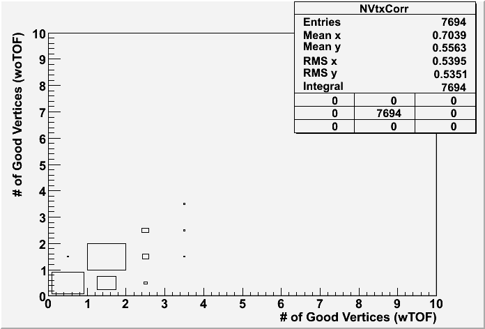
Fig. 6: The ranking distributions for all vertices from PPV w/ and w/o TOF (left) and also the correlation between the funnyR values for the first primary vertex in two cases. (200 GeV)
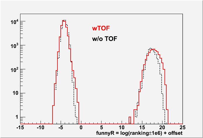
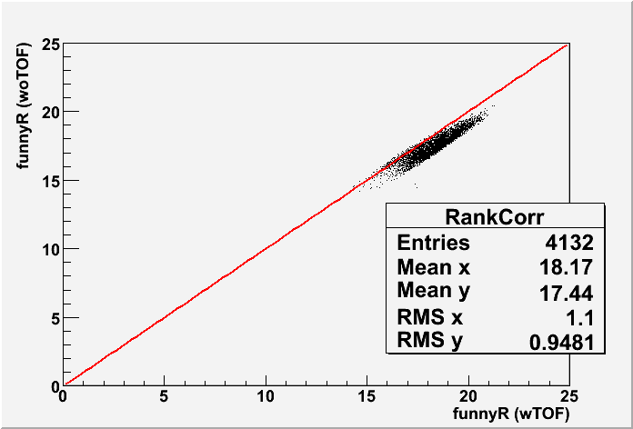
Fig. 7: Vz correlation for the good vertex (ranking>0) with the highest ranking in each event for PPV w/ and w/o TOF (200 GeV).
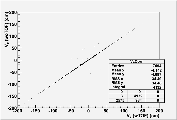
Fig. 8: Vz difference between vertices found in PPV w/ TOF and w/o TOF for the first good vertex in each event if any (200 GeV)
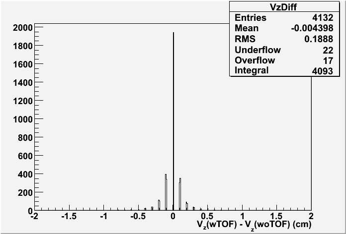
Conclusion:
The above tests with real data have shown the expected PPV performance with inclusion of BTOF hits.
BTOF Operations
Note that the only authoritative location of operations information for BTOF (and other subsystems) is at https://drupal.star.bnl.gov/STAR/public/operations
This page only serves as a short cut to (recent) BTOF-related operations manuals. Always check the date and consult with the BTOF experts in case of any doubt.
- TOF/MTD General Instructions (updated 05-Sep-2024)
- TOF Gas Bottle Switchover Procedure (updated 2024 Jul 15)
- TOF Pow Cycle Procedures (Run2023), [TOF Power Cycle Procedure(Old version with Anaconda)]
- TOF LVIOC Restart Procedure
- TOF/MTD HV IOC Restart Procedure (Updated 2023)
- MTD Power Cycle Procedure (Run2022), [ MTD Power Cycle Procedure (Old version with Anaconda)]
- MTD LVIOC Restart Procedure
- Canbus Restart Procedure, [Canbus Restart Procedure (Old version with Anaconda)]
- Solve MTD (eTOF) Isobutane Fraction Alarm Instructions
BTOF Simulations
Barrel TOF/CTB Geometry Configurations
The definitions of Barrel TOF/CTB geometry configurations are shown here:
BtofConfigure = 1; /// All CTB trays
BtofConfigure = 2; /// All TOFp trays
BtofConfigure = 3; /// big TOFp path (trays from 46 to 60), rest are CTB trays
BtofConfigure = 4; /// Run-2: one TOFp tray (id=92), rest CTB
BtofConfigure = 5; /// Run-3: one TOFp (id=92) tray and one TOFr (id=83) tray, rest CTB
BtofConfigure = 6; /// Full barrel MRPC-TOF
BtofConfigure = 7; /// Run-4: one TOFp (id=93) tray and one TOFr (id=83) tray, rest CTB
BtofConfigure = 8; /// Run-5: one TOFr5 (id=83) tray, rest CTB
BtofConfigure = 9; /// Run-6: same as Run-5
BtofConfigure = 10; /// Run-7: same as Run-5
BtofConfigure = 11; /// Run-8: Five TOFr8 trays (id=76-80), rest CTB
BtofConfigure = 12; /// Run-9: 94 installed trays, rest slots are empty
TOF selections in different geometry tags should be in the followints:
year 2002: Itof=2; BtofConfigure=4;
year 2003: Itof=2; BtofConfigure=5;
year 2004: Itof=2; BtofConfigure=7;
year 2005: Itof=4; BtofConfigure=8;
year 2006; Itof=5; BtofConfigure=9;
year 2007: Itof=5; BtofConfigure=10;
year 2008: Itof=6; BtofConfigure=11;
year 2009: Itof=6; BtofConfigure=12;
All geometry in UPGRxx should use BtofConfigure=6 (full TOF configuration).
TOF Simulation Resolution Database
Database
These pages describe how to use the Barrel TOF (including VPD) database.
One can use the following browser to view the TOF tables: http://www.star.bnl.gov/Browser/STAR/browse-Calibrations-tof.html
More information on how to access the various (TOF) databases can be found in the Offline DB Structure Explorer at the following link: http://online.star.bnl.gov/dbExplorer/
Add a flag in vpdTotCorr.idl for noVPD start calibration switch
In low energy runs, the VPD acceptance and efficiency becomes a potential issue. We are planning to develop a barrel TOF self calibration algorithm based on only the hits on the barrel trays (we call it non-vpd-start calibration). The calibration constant structures should be similar as the conventional calibration using vpd for the start time. But certainly the algorithm in applying these constants will be different. We thus need to introduce an additional flag in the calibration table to tell the offline maker to load the corresponding algorithm then. The proposed the change is on the vpdTotCorr.idl table. The current structure is like this:
struct vpdTotCorr {
short tubeId; /* tubeId (1:38), West (1:19), East (20:38) */
float tot[128]; /* edge of tot intervals for corr */
float corr[128]; /* absolute corr value */
};
We would like to add another short variable "corralgo", then the modified idl file should be like this:
struct vpdTotCorr {
short tubeId; /* tubeId (1:38), West (1:19), East (20:38) */
float tot[128]; /* edge of tot intervals for corr */
float corr[128]; /* absolute corr value */
short corralgo; /* 0 - default vpd-start calibration algorithm */
/* 1 - non-vpd-start calibration algorithm */
};
We will make the corresponding modifications to the StVpdCalibMaker and StBTofCalibMaker to implement the new calibration algorithm.
Proposal of new TOF tables for Run9++ (Jan. 2009)
We are proposing to create several new TOF tables for future full barrel TOF runs.
Draft IDLs:
/* tofINLSCorr
*
* Tables: tofINLSCorr
*
* description: // INL correction tables information for TOF TDIGs (in short)
*/
struct tofINLSCorr {
short tdigId; /* TDIG board serial number id */
short tdcChanId; /* tdcId(0:2)*8+chan(0:7) */
short INLCorr[1024]; /* INL correction values */
};
INDEX: trayCell [ table: trayCellIDs ], range: [1 .. 30000]
Note: This table is an updated one from the previous tofINLCorr. Considering the considerable I/O stream load for this table in future full system, we changed the precision of the correction values from float to short (the value will be stored as (int)(val*100)). From the intial test, we won't lose any electronic resolution.
/* tofGeomAlign
*
* Tables: tofGeomAlign
*
* description: // tof alignment parameters for trays, trayId will be
* // indicated as the elementID (+1) in data base
*/
struct tofGeomAlign {
float z0; /* offset in z */
float x0; /* offset in radius */
float phi0; /* offset in phi (local y direction) */
float angle0; /* tilt angle in xy plane relative to ideal case */
};
INDEX: trgwin [ table : trgwinIDs ], range : [1..122]
Note: This table contains the necessary geometry alignment parameters for real detector position shifting from the ideal position in GEANT. The trayId will be indicated as the elementID in the database.
/* tofStatus
*
* Tables: tofStatus
*
* description: // tof status table
*/
struct tofINLCorr {
unsigned short status[24000]; /* status code */
};
INDEX: None
Note: TOF status table. The definition of the status code is being finalized.
/* tofTrgWindow
*
* Tables: tofTrgWindow
*
* description: // tof trigger timestamp window cuts to select physical hits
*/
struct tofTrgWindow {
unsigned short trgWindow_Min; /* trigger time window cuts */
unsigned short trgWindow_Max; /* trigger time window cuts */
};
INDEX: trgwin [ table: trgwinIDs ], range: [ 1 .. 122 ]
Note: TOF trigger time window cuts to seletect physical hits. There will be 120 (trays) + 2 (E/W Vpds) elements in total.
Load Estimate
tofINLSCorr: There will be one row for each channel. In total for full barrel system, there will be ~24000 rows. We also have some spare boards, to have all in one place, the maximum # of rows is better to set as 30000. The total load size for DB I/O will be ~30000*1024*2 Byte ~ 60 MB
tofGeomAlign: There will be 120 rows in each fill. The load size is negligible.
tofStatus: All channels are combined in a single array.
tofTrgWindow: 120+2 elements.