Technical information

| Run 15 preparation Photographs of crates Roman Pot naming convention |
Trigger
|
| Alignment |
DAQ-expert materials Packages tests (Si + trig.count.) Trigger counters tests |
DAQ-expert materials
Test of Si detector packages:
A-6 A : STAR/system/files/userfiles/2729/file/Assembly_test/Assembly_A6_detAcorrect.pdf
A-6 B : STAR/system/files/userfiles/2729/file/Assembly_test/Assembly_A6_detBcorrect.pdf
A-6 C : STAR/system/files/userfiles/2729/file/Assembly_test/Assembly_A6_detCcorrect.pdf
A-6 D: STAR/system/files/userfiles/2729/file/Assembly_test/Assembly_A6_detDcorrect.pdf
A-6 Trigger system: STAR/system/files/userfiles/2729/file/Assembly_test/A_6_cosmic.pdf
A-1 A: STAR/system/files/userfiles/2729/file/Assembly_test/AssemblyA1_detA(1).pdf
A-1 B: STAR/system/files/userfiles/2729/file/Assembly_test/Assembly_A1_detB(1).pdf
A-1 C: STAR/system/files/userfiles/2729/file/Assembly_test/Assembl_A1_detC.pdf
A-1 D: STAR/system/files/userfiles/2729/file/Assembly_test/Assembl_A1_detD.pdf
Trigger system for A-1 assembly: STAR/system/files/userfiles/2729/file/Assembly_test/PMT_A1.pdf
A-4 A: STAR/system/files/userfiles/2729/file/Assembly_test/Assembly_A_4_detA.pdf
A-4 B: STAR/system/files/userfiles/2729/file/Assembly_test/Assembly_A_4_detB.pdf
A-4 C: STAR/system/files/userfiles/2729/file/Assembly_test/Assembly_A4_detC.pdf
A-4 D: STAR/system/files/userfiles/2729/file/Assembly_test/Assembly_A4_detD.pdf
Trigger system for A-4 assembly: STAR/system/files/userfiles/2729/file/Assembly_test/PMT_A_4.pdf
B-1 A: STAR/system/files/userfiles/2729/file/Assembly_test/Assembly_B1_detA.pdf
B-1 B: STAR/system/files/userfiles/2729/file/Assembly_test/Assembly_B_1_detB.pdf
B-1 C: STAR/system/files/userfiles/2729/file/Assembly_test/Assembly_B_1_detC(1).pdf
B-1 D: STAR/system/files/userfiles/2729/file/Assembly_test/Assembly_B_1_detD.pdf
Trigger system for B-1 assembly: STAR/system/files/userfiles/2729/file/Assembly_test/B_1_cosmic.pdf
B-2 A: STAR/system/files/userfiles/2729/file/Assembly_test/Assembly_B2_detA.pdf
B-2 B: STAR/system/files/userfiles/2729/file/Assembly_test/Assembly_B_2_B.pdf
B-2 C: STAR/system/files/userfiles/2729/file/Assembly_test/Assembly_B_2_C.pdf
B-2 D: STAR/system/files/userfiles/2729/file/Assembly_test/Assembly_B_2_D.pdf
Trigger system for B-2 assembly: STAR/system/files/userfiles/2729/file/Assembly_test/PMTB2.pdf
B-4 A: STAR/system/files/userfiles/2729/file/Assembly_test/Assembly_B4_detA.pdf
B-4 B: STAR/system/files/userfiles/2729/file/Assembly_test/Assembly_B4_detB.pdf
B-4 C: STAR/system/files/userfiles/2729/file/Assembly_test/Assembly_B4_C.pdf
B-4 D: STAR/system/files/userfiles/2729/file/Assembly_test/Assembly_B4_detD.pdf
Trigger system for B-4 assembly: STAR/system/files/userfiles/2729/file/Assembly_test/B_4_cosmic.pdf
B(A)-5 A: STAR/system/files/userfiles/2729/file/Assembly_test/Assembly_BA5_detA.pdf
B(A)-5 B: STAR/system/files/userfiles/2729/file/Assembly_test/Assembly%20_BA5_detB.pdf
B(A)-5 C: STAR/system/files/userfiles/2729/file/Assembly_test/Assembly_BA5_detC.pdf
B(A)-5 D: STAR/system/files/userfiles/2729/file/Assembly_test/Assembly_BA5_detD.pdf
Trigger system for B(A)-5 assembly: STAR/system/files/userfiles/2729/file/Assembly_test/PMT_BA5.pdf
A-3 A: STAR/system/files/userfiles/2729/file/Assembly_test/Assembly_A3_detA.pdf
A-3 B: STAR/system/files/userfiles/2729/file/Assembly_test/Assembly_A3_detB.pdf
A-3 C: STAR/system/files/userfiles/2729/file/Assembly_test/Assembly_A_3_detC.pdf
A-3 D: STAR/system/files/userfiles/2729/file/Assembly_test/Assembly_A3_detD.pdf
A-3 Trigger system: STAR/system/files/userfiles/2729/file/Assembly_test/A_3_cosmic.pdf
------------------------------------------------------------------------------------------------------------------------------------------------------------------------------------------------------------------
Test of trigger counters:
Setup
Test of the trigger counters was performed using (see first photo):
- high voltage power supply,
- Tektronix MSO 3034 Mixed Signal Oscilloscope,
- beta radiation source 90Sr.
Trigger counters were left in the storage boxes to avoid possible damages. Both PMTs in the counter were supplied with the same voltage, which was changed in a range 800-1200 V. Beta source was always sitting on the surface of the scintillator, pointing to it (like on the second photo). Measurements were done with the source in a few different points on the surface of the scintillator, in order to determine position dependencies. As shown in the third photograph, storage boxes with trigger counters were additionally placed inside the folder with zipper to fully avoid influence of the external light.
In order to enable offline analysis, some number of waveforms from both channels (PMTs) was stored on a USB flash memory in *.isf format (internal save format of the scope). Then, isf files were converted into ROOT histograms and processed (contact me to get the converting program).
Dark noise measurement
This measurement was done without use of the 90Sr source. Signals were triggered with very low threshold value (order of mV, depends on supplying voltage). The lack of signal in the PMT other than the triggering one (like on the figure below; red = channel 1, blue = channel 2) was a confirmation for non-cosmic-ray origin of the pulse.

For such events the dark-noise peak amplitudes were histogramed. Links to plots of these histograms are contained below.
A-3 A-6 B(A)-5 B-1
As an output the dark noise levels as a function of the supplying voltage were prepared for each channel separately: DARK NOISE vs. VOLTAGE.
Detailed tests with 90Sr source - part 1
The main part of the test was done with the beta source placed in three points on the scintillator, as shown in red on the right-hand side sketch. For each position of the source and each PMT voltage, about 150 triggers were collected. The triggering threshold was set to ~2sigma above the noise level, based on the dark noise measurement (see above). Only one of the channels was set to trigger. An exemplary output from oscilloscope is presented in the left-hand side figure (below), together with description of quantities whose distributions are available in the table below.


| quantity \ counter | A-3 | A-6 | B(A)-5 | B-1 |
|---|---|---|---|---|
| Signal amplitudes (correlation between channels and 1-D amplitude distributions) |
||||
| Signal integrals (correlation between channels and 1-D integral distributions) |
||||
| Time difference between moments of reaching the threshold by signals in two channels |
||||
| Rise time (correlation between channels and 1-D rise time distributions) |
||||
| Fall time (correlation between channels and 1-D fall time distributions) |
Explanation of quantities from the table:
Signal amplitude is nothing but the maximum absolute value of the pulse (at peak).
Signal integral is simply an integral of the pulse over time.
Time difference (\delta t, difference in time of discrimination) is the time interval between the moment of reaching the threshold level by the pulses in two channels (see the left figure above).
Rise time is defined as the time interval for the pulse to reach 10% and 90% of its peak value (see the left figure above).
One should note, that the time difference contains a component which depends e.g. on the lenght of wires connecting PMTs with the oscilloscope, so only the relative time difference ("difference between time differences") should be studied.
Detailed tests with 90Sr source - part 2
The second part of the tests was also done with the use of beta source, this time however a more detailed position dependence (11 different points) of the pulse properties was checked. For each position of the source and supplying voltage only one waveform (for each channel) was saved (instead of ~150 as in part 1), however, a waveform itself was an average of 512 triggered pulses (the same trigger thresholds were set for corresponding voltages as in part 1). Examples of the average pulses from two channels are presented in figure below. Results of the 2nd part of tests are contained in the table below.

| quantity \ counter | A-3 | A-6 | B(A)-5 | B-1 |
|---|---|---|---|---|
Average-signal amplitudes |
||||
Time difference (for average signals) |
The black contour in the plots in the table above marks the area of the scintillator (8 cm x 5 cm). Colours of markers correspond to the value of presented quantity (see description of z-axis).
Detector package information
Each cell in the table below corresponds to single package (as it was assembled in 2009), whose label is given at the top of the cell.
Two tables at the bottom of the page indicate the Roman Pot in which components
of each particular package (silicon planes - A, B, C and D, and trigger counter - TC)
were installed during run 2009 and 2015.
|
A-3
Run 2009 performance: SVX pedestals:
Cluster properties (silicon data):
Trigger counter:
Pre-2015 tests:
SVX ped. and cluster properties:
Trigger counter:
|
B-4
Run 2009 performance: SVX pedestals:
Cluster properties (silicon data):
Trigger counter:
Pre-2015 tests:
SVX ped. and cluster properties:
Trigger counter:
|
A-1
Run 2009 performance: SVX pedestals:
Cluster properties (silicon data):
Trigger counter:
Pre-2015 tests:
SVX ped. and cluster properties:
Trigger counter:
|
B-1
Run 2009 performance: SVX pedestals:
Cluster properties (silicon data):
Trigger counter:
Pre-2015 tests:
SVX ped. and cluster properties:
Trigger counter:
|
|
B(A)-5
Run 2009 performance: SVX pedestals:
Cluster properties (silicon data):
Trigger counter:
Pre-2015 tests: SVX ped. and cluster properties:
Trigger counter:
|
A-6
Run 2009 performance: SVX pedestals:
Cluster properties (silicon data):
Trigger counter:
Pre-2015 tests:
SVX ped. and cluster properties:
Trigger counter:
|
B-2
Run 2009 performance: SVX pedestals:
Cluster properties (silicon data):
Trigger counter:
Pre-2015 tests:
SVX ped. and cluster properties:
Trigger counter:
|
A-4
Run 2009 performance: SVX pedestals:
Cluster properties (silicon data):
Trigger counter:
Pre-2015 tests:
SVX ped. and cluster properties:
Trigger counter:
|
| E1U | E1D | E2U | E2D | W1U | W1D | W2U | W2D | |
| A | B-4 | A-3 | B-1 | Spare | A-4 | B(A)-5 | A-1 |
B-2
|
| B | B-4 | A-3 | B-1 | A-6 | A-4 | B(A)-5 | A-1 | B-2 |
| C | B-4 | A-3 | B-1 | A-6 | A-4 | B(A)-5 | A-1 | B-2 |
| D | B-4 | A-3 | B-1 | A-6 | A-4 | B(A)-5 | A-1 | B-2 |
| TC | B-4 | B-1 | A-4 | A-6 | A-3 | B(A)-5 | A-1 | B-2 |
| EHI | EHO | EVU | EVD | WHI | WHO | WVU | WVD | |
| A | A-3 | B-4 | A-1 | B-1 | B(A)-5 | A-6 | B-2 |
A-4
|
| B | A-3 | B-4 | A-1 | B-1 | B(A)-5 | A-6 | B-2 | A-4 |
| C | A-3 | B-4 | A-1 | B-1 | B(A)-5 | A-6 | B-2 | A-4 |
| D | A-3 | B-4 | A-1 | B-1 | B(A)-5 | A-6 | B-2 | A-4 |
| TC | A-3 | B-4 | A-1 | B-1 | B(A)-5 | A-6 | B-2 | A-4 |
Operation instructions
Power to most of the STAR Roman Pot systems can be controlled remotely with two APC Switched Rack Power Distribution Units. Individual outlets on each rack can be turned on or off using a browser pointing to the following IP a11ddress (inside the BNL firewall):
East Roman Pots: 130.199.90.26
West Roman Pots: 130.199.90.38
A browser running on ppdaq1.phy.bnl.gov (in STAR Control room) is the prefered link to the APC, if there is a need for remote access, a connection to a NX server will give you access to a window whwre you can launch FireFox and access the URLs listed above.
Only one connection is possible to the APC, but the connections time-out after 1 minute without action
Once a connection to the APCs is established you will be asked for user name and password.
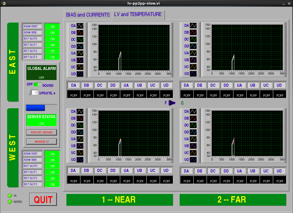
A LabView based monitor system called lv-pp2pp-slow runs a server in the ppdaq1.phy.bnl.gov computer. Clients communicate with the server to display the status of the bias and low voltage power supplies and the relevant values of voltages, currents and temperatures. One can run a client remotely by first connecting to a BNL gateway (rssh.rhic.bnl.gov) and from there login into ppdaq1.phy.bnl.gov from the daq account. (All necessary passwords need to be requested from relevant people). The client program is then launched by ~/bin/lv-ppslow &. The following window will open on you computer:

When a board fails (blown fuse or other problem we need to change the pp2pp-slow.conf and use the variable SiIgnore at the end of the file. That variable uses 32 bits which correspond to all planes as listed in the file (Plane00 correspond to the least significant bit SiIgnore = 0x00000001 and so on. This only masks out the alarm on the OneButton GUI below and the alarms (one on LV channel in question and another one on the "Global Alarm" section) would still appear in the the above GUI (lv-ppslow).
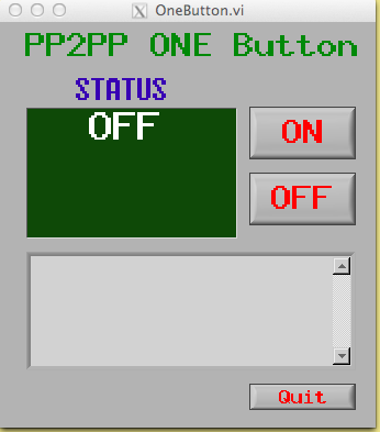
Shift crew Detector operators will interact with Roman Pots thru the "Single button" client:

Which appears above in the off position.
This window is activated with the icon:
what to do if the icon has dissapeared from the Desktop?
Possible faults as seen in the "single button" client.
Persistent Blue field:
Red Alarm:
There is also a "command line" monitor which has funcionality to peform many actions, it is called pp2pp_cmd. A snippet of the code gives you a list of all its functionality:

If there is a need to modify the pp2pp daq configuration files one needs to login as evpops (not "operator" since early 2017) on daqman.starp.bnl.gov. To reach that computer you have to be inside BNL firewall and login into the STAR gateway with your certificates (ssh -Y -A username@stargw.starp.bnl.gov). Or, you may "ssh -i ~pp2pp/.ssh/skm-key-yipkin-daqman.starp.bnl.gov evpops@daqman" from our workstation blanchett in the STAR Control Room (and ask Kin Yip for the ssh passphrase). The configuration files are in:
/RTS/conf/pp2pp/pp01.ini for the East Roman Pots,
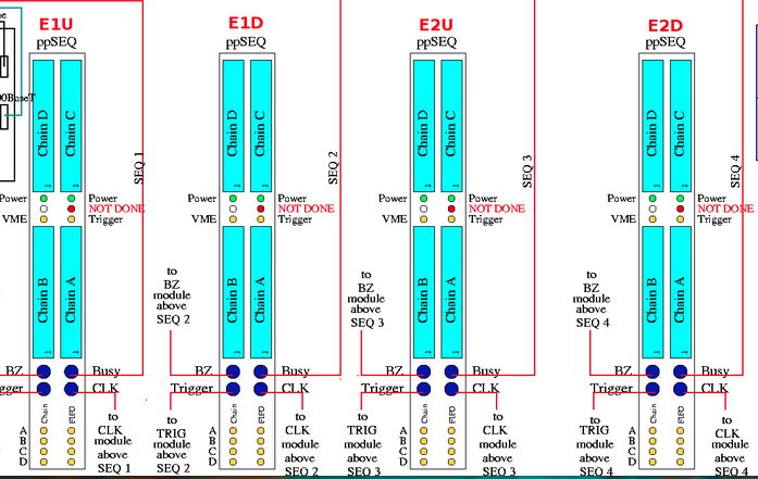
as a reminder of which RP plane is connected to a particular sequencer use this figure:

As is shown in the figure below, each sequencer uses 4 bits to indicate which detector (plane, chain) is active and will be read. Example all planes are active 0xF

if chain D failed in E1D one should have 0x7 in ppSEQ02
/RTS/conf/pp2pp/pp02.ini for the West Roman Pots
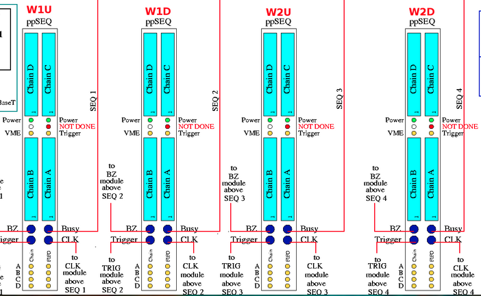
as a reminder of which RP plane is connected to a particular sequencer use this figure:

with the corresponding variables in pp02.ini:

The cameras are at 130.199.90.6 East (air flow) 130.199.90.7 (electronics rack)
130.199.90.9 (air flow) 130.199.90.22 ElectronicsWest
East air flow: 130.199.90.6/home/homeS.html
East electronics rack 130.199.90.7/home/homeS.html
West air flow: 130.199.90.9/home/homeS.html
West electronics rack: 130.199.90.22/home/homeS.html
Igor/Dima's trick in checking the LV quickly from the command line (which is the same set commands that the pp2pp-slow-server.c uses):
In ppdaq1, we need two terminals.
- In one terminal (like "xterm"), do
"stty -F /dev/vttyAP1 time 1 min 1" and then "cat /dev/vttyAP1" (for the East), OR
"stty -F /dev/vttyAP3 time 1 min 1" and then "cat /dev/vttyAP3" (for the West),
and wait;
- In another terminal, do:
echo -ne '$00A\r' >> /dev/vttyAP1 (for the East) OR
echo -ne '$00A\r' >> /dev/vttyAP3 (for the West) ;
- Watch the first terminal for any output. If that power board/card exists, we should see a reading (output); otherwise, this may indicate that there is no such power board, when all the cables (including the relevant serial link !) have been connected.
- 'A' : AVDD1 volt reading
- 'B' : AVDD2 volt reading
- 'C' : DVDD volt reading
- 'D' : DPECL volt reading
Igor's quick initialization check:
After logging to operator@pp01-l or operator@pp02-l (from daqman.starp.bnl.gov for example),
- cd /RTS/IGOR
- Edit ppSEQ.ini to set the sequencer(s)/chain(s) that you want to initialize (just like pp01.ini/pp02.ini in /RTS/conf/pp2pp).
- ./pprun
- When working, you should see the least significant number after "read" to fluctuate between 0 and 1 when the number after "expect" changes between 2 and 3.
Running pedestal:
- Get an account for blanchett.starp.bnl.gov (by asking Wayne Betts or Michael Poat and also requesting your account be put under the "pp2pp" group).
- cd /home/pp2pp
- ./pedestal.csh run_no
- Hit return to see all the pedestals and rms' for all chains. The figures, 8 for pedestals and 8 for rms', are stored as seq_1.gif ... seq_8.gif and rms_seq_1.gif ... rms_seq_8.gif.
Looking for hints in DAQ Monitoring log files (/log/esb.log in daqman) :
- When you found errors when using the RunControl of STAR to take data, you may go to daqman.starp.bnl.gov (one can login with the operator account) to find more detailed error messages.
For example, one can do the following to find out problems related to pp02 :
grep pp02 /log/esb.log
and one might see:
[pp02-l 17:35:36 016] (pp2ppMain): ERROR: ppSEQ.C [line 98]: FAILURE: ppSEQ07: Switching to EXT clocks failed
This means that something was wrong with the clock connection to the sequencer #7.
-
A hint for which VME to reboot in /log/esb.log or /log/daq.log in daqman or in STAR Run Control Panel:
The first example may be seen in the STAR Run Control panel (used by the STAR Shifters) or in /log/esb.log
esb.log:[pp01-l 08:32:39 060] (pp2ppMain): CRITICAL: det.C [line 140]: PP2PP: RDO 1 -- too many auto-recoveries. Stopping!
esb.log:[pp01-l 08:32:49 060] (pp2ppMain): CRITICAL: esbTask.C [line 2458]: Recovery failed for RDO(s): 1 -- stopping run!
If one sees the above the "CRITICAL" message for pp01-l, one knows that it's the pp01-l (VME) in the East that's at fault and so we should reboot that VME crate. { From Tonko, this one was due to crashes in one of the sequencers and we got a message of failed recovery as there is NO recovery possible ! }
Another example, either in the Run Control panel or /log/daq.log, one might see:
daq.log:[daqman 14:14:39 065] (scDeamon): CRITICAL: scDeamon.C [line 1218]: PP2PP[1] [0x6111] Rebooted
In this case, from Tonko, "PP2PP[1]" also pointed out thtat pp01-l (VME) should be rebooted. Also from Tonko, we got this message that said "CPU rebooted" because either the CPU or the Ethernet had crashed.
-
Also, we don't need to worry about the the "ERROR" messages about "External clock" such as :
esb.log:[pp02-l 11:06:51 060] (pp2ppMain): ERROR: ppSEQ.C [line 97]: ppSEQ05: External clock reqired, but lost, status 0x80520C0F, trying to fix
esb.log:[pp01-l 11:06:51 060] (pp2ppMain): ERROR: ppSEQ.C [line 97]: ppSEQ03: External clock reqired, but lost, status 0x80520C0F, trying to fix
Tonko said: "Yes, the loss of clock seems to happen fairly often. It happens to both sides (crates) at the same time so it must be somehow related to the driver module at the TCD end. But it doesn't seem to cause any issues.Also, you will see this message at EVERY run-stop because of the way clock switch-over is sequenced. But this is completely innocuous because the run has already stopped."
In the Control Room, one usually just goes over to the terminal for the sc5 node. But if one wants to remotely change the HV's, one may login from any starp gateway/node (such as our "blanchett"),
- ssh sysuser@sc5 and find the password (for sysuser) from the folder in the STAR Control Room ;
- enter the alias command "pp2pphv" on the command prompt ;
[ From a home computer or whatever, pp2pphv may abort. So, instead of doing
"medm -displayFont scalable -x /home/sysuser/GUI/trg/pp2pp.adl" (which is what "pp2pphv" does), you may do:
medm -displayFont alias -x /home/sysuser/GUI/trg/pp2pp.adl ]
- a "PP2PP HV Controls" panel would pop up ;
- by putting the cursor on top of the "demand voltage" field of the relevant channel , one can type in to raise the voltages (such as 1100 V).
Moving Roman-Pots using the "pet" page:
One should communicate with the MCR first and gain their approval before you can move the roman-pot; otherwise, illegal roman-pot movement may result in complete beam loss.
If it's not already opened for you, you may go to any of the following "pet" page to try to move roman-pots.
- "pet" → "RHIC" → "Interaction_Regions" → "PP2PP" → "RomanCtrl" → "Sector 5" (East) or "Sector 6" (West)
OR
- "pet" → "RHIC" → "Drives" → "romanPots" → "Sector 5" (East) or "Sector 6" (West)
The two pet pages are mostly the same and we probably use the first one mostly, as the first one provides plots of the NMC radiation levels. [ But the second one allows one to re-enable the motor drive permit (by clicking "disable" and then "enable", at the bottom of each page) that the first one doesn't. This may be needed after one moves the roman-pot back to retracted position after finishing some work during an access or maintenance etc. ]
There are 4 stations on each page and we should just pay attention to the familiar names of ours such as E1U, E1D etc. For each plot, one should see "LVDT Top" or "LVDT Bottom" (under "Position Measurements"), and at the fully retracted positions, that number should about ±89 mm.
For each pot, in order to move a pot, go to the space below the word "step cmd" and type in the "absolute" (not incremental) no. of steps to move the pot. 1 mm needs about 8000 steps. ( It's "0" if the pot is fully retracted. ) After typing in the no. of steps, you should see the absolute number of 87 mm decrease. Eg. if 87 mm changes to 85 mm, it indicates that the pot has moved 2 mm towards the center of the beam pipe. To move more, you need to type in a bigger "number of steps".
The hard stop is 15 mm from the center (0 mm) but the limiting switch would limit the pot movement to around 16.5 mm or so.
To go back to the fully retracted position, just hit "home" for that pot.
In the unlikely event that you want to AC-reset APC or network equipment inside the tunnel, you may go to the following pet page area:
- "pet" → "RHIC" → "Interaction_Regions" → "PP2PP" → "RomanCtrl" → "ACresets"
On each side (East/yo5 or West/bo6), you may "AC reset" the power of the APC (apc.acpwr) or Network Switch (nw.acpwr) or Magnum Converter (mc.acpwr). Magnum Converter converts between Ethernet signals and optical signals.
Cronjob in ppdaq1.phy.bnl.gov
There is a cronjob in /etc/cron.d/pp2pp-slow:
# Check pp2pp slow server every 2 minutes
*/2 * * * * daq /home/daq/pp2pp-slow/check-server.sh >> /dev/null
which checks whether the server is running or not and restarts it if not.
During shutdown, it may be kept as a hidden file /etc/cron.d/.pp2pp-slow (noticing the "." before "pp2pp-slow").
One can use the serial/DIGI link to look at the reboot of the VME in the tunnel, the instructions have been written in:
https://romanpot-logbook.phy.bnl.gov/Romanpot/25
West: 130.199.90.120
Restarting network daemon in ppdaq1.phy.bnl.gov:
One should do :
service NetworkManager restart
NOT
!!
Check lists for Installation and Repair of Roman Pot assemblies STAR/system/files/userfiles/2729/file/Assembly_test/installRP(2).pdf
Running TCD manually:
http://online.star.bnl.gov/daq/export/TCD_WWW/index.html?client=tcd-pp2pp
Goto "Scheduler" and select "Start". User name: star_tcd.
Run 15 preparation
| Documents Roman Pot naming convention |
|
| Drawings / Schemes / Pictures Photographs of crates on EAST and WEST |
Map of connections
East   |


